
Generation of variable differential group delay

a technology of differential group delay and variable, applied in the direction of instruments, polarising elements, optical elements, etc., can solve the problems of limiting the deployment of new systems over the older fibre route, polarisation mode dispersion, pmd,

Inactive Publication Date: 2005-01-11
CIENA
View PDF3 Cites 25 Cited by
  • Summary
  • Abstract
  • Description
  • Claims
  • Application Information

AI Technical Summary

Benefits of technology

This arrangement enables a large number of birefringent elements to be used (thus enabling a large net total PMD compensation to be achieved) with only two rotator devices being under control at any time to provide a varying level of PMD compensation. This simplifies the control scheme.
Preferably, a first set of orientations provides zero DGD and a second set of orientations provides maximum DGD, wherein the orientations for all birefringent elements are 0 or 90 degrees for the first and second sets. In order to vary between DGD of 0 and the maximum, at most two control devices are operated at any time, and the control steps the compensator monotonically through all values between the minimum (zero) and maximum DGD values. This provides a linear and simple control scheme.

Problems solved by technology

Various potential limits are approached as the performance of such transmission systems is pushed further.
The phenomenon of polarisation mode dispersion, PMD, is a problem recently attracting a great deal of attention from the telecommunications industry.
Whilst service providers are reluctant to invest in new fibre routes, PMD may restrict the deployment of new systems over the older fibre routes of their network.
In a small number of fibres, PMD will give rise to distortions so large that a 10 Gbit / s optical transmission system cannot be reliably deployed over the route.
The impact of PMD scales linearly with system bit-rate, hence PMD will become a greater problem as the bit-rate of systems are increased.
The difference in arrival times of the pulse through the two polarisation modes will degrade the quality of the received data.
For bit interleaved signals, the all-optical PMD compensator described above has limited efficacy.
However, the control of the polarization rotators in such arrangements has in the past been complicated.
A further problem which can arise from the use of a first-order PMD compensator is that second (and higher) order PMD is worsened by the compensator arrangement.

Method used


Image

  • Generation of variable differential group delay
  • Generation of variable differential group delay
  • Generation of variable differential group delay

Examples


Embodiment Construction

The invention provides various architectures for providing variable DGD. As discussed above, one specific use of an arrangement which provides variable DGD is in PMD compensators, and the description below is in connection with such PMD compensators.

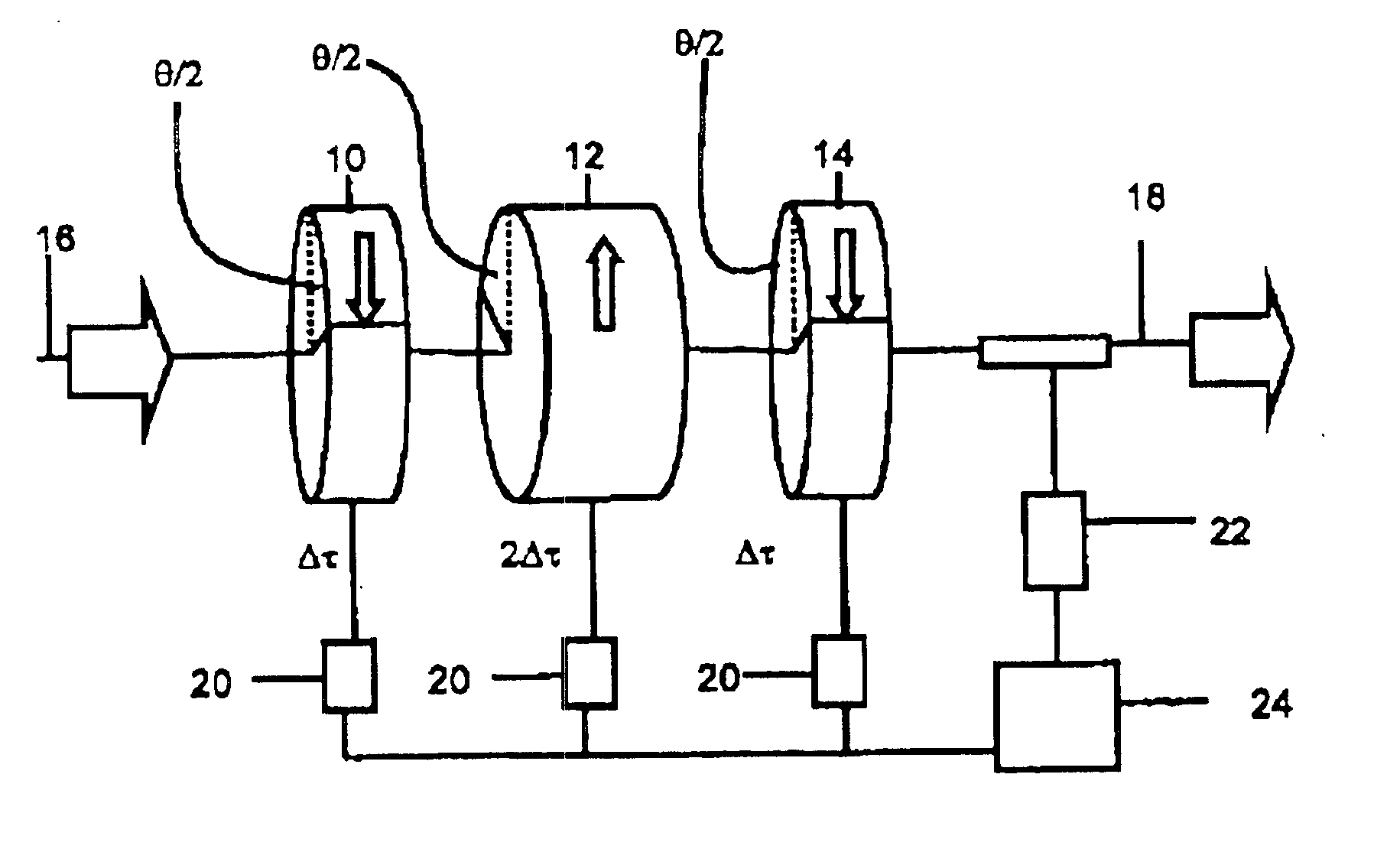
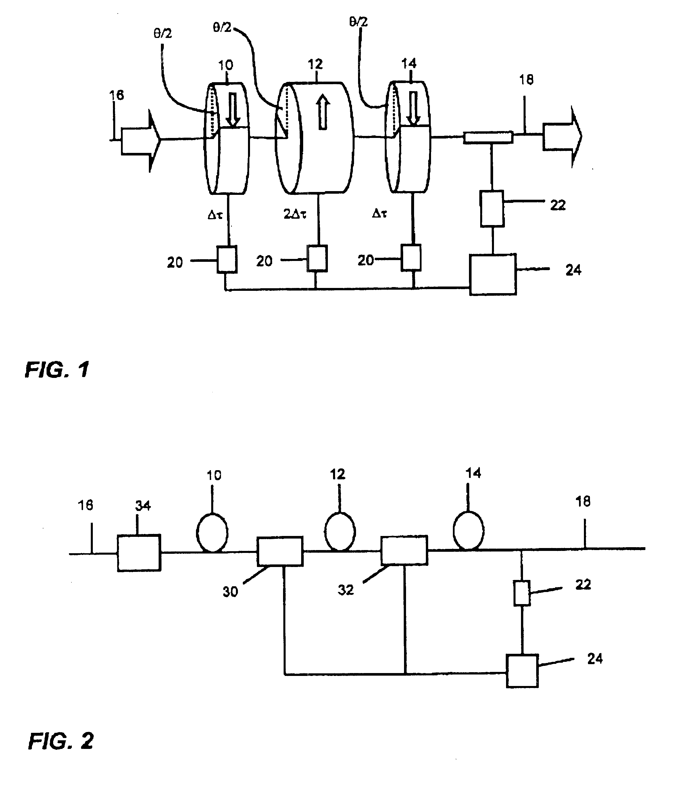
The first aspect of the invention provides a polarization mode dispersion (PMD) compensator which is designed to provide first order PMD compensation with no second order PMD penalty. The compensator of the invention may be implemented in various ways. FIG. 1 shows one such implementation.

The compensator of FIG. 1 comprises first, second and third birefringent elements 10, 12, 14 arranged in order between the input 16 and output 18 of the compensator. The elements have first, second and third DGDs, respectively, in the ratio 1:2:1, as shown in FIG. 1. For example, the elements may have the same birefringence, but have lengths in the ratio 1:2:1. Each birefringent element has two orthogonal principal axes, which are the axes of maximum an...


PUM


Abstract

An apparatus for generating variable DGD is particularly for use in a PMD compensator. The apparatus has first, second and third birefringent elements arranged in order between the input and output of the compensator and having first, second and third differential group delays (DGDs) in the ratio 1:2:1. The orientation of the PSPs of the signal in each element relatively to the principal axes of the element is controlled, such that a change in orientation between the first and second elements is equal and opposite to a change in orientation between the second and third elements. This arrangement provides symmetrical relative rotations of the signal PSPs and principal axes about the central birefringent element. In combination with the 1:2:1 ratio, it can be shown that compensation of any first order PMD can be achieved without the compensator introducing additional second order PMD. The required level of first order PMD compensation is selected by controlling the amount of the orientation changes.

Description

FIELD OF THE INVENTIONThis invention relates to apparatus and methods for generating variable differential group delay, for example for providing Polarization Mode Dispersion (PMD) compensation in high-speed optical transmission networks and systems.BACKGROUND TO THE INVENTIONFibre-optic transmission systems are now being developed for tens of gigabits-per-second (Gbit / s) communication channels, whilst large volumes of 10 Gbit / s systems are being fully deployed into existing networks. Various potential limits are approached as the performance of such transmission systems is pushed further. The phenomenon of polarisation mode dispersion, PMD, is a problem recently attracting a great deal of attention from the telecommunications industry. PMD is a type of distortion that varies from fibre to fibre and is typically of greater magnitude in older fibres. PMD is also a random phenomenon, varying with both time and optical frequency. Whilst service providers are reluctant to invest in new ...

Claims


Application Information

Patent Timeline
IPC IPC(8): G02F1/01G02B27/28G02B6/34H04B10/18
CPCG02B6/278H04B10/2569G02F1/0136G02B27/286
Inventor SAVORY, SEBASTIAN JGUO, QINGHAWRYLUCK, MARK ALAROSE, ROBERT
Owner CIENA
Learn More