Apparatus including a boom to be compressed and rolled up

a technology of compressing and rolling up booms, which is applied in the direction of cranes, transportation and packaging, and cosmonautic vehicles. it can solve the problems of substantial expenditure for fixing the drum after unfolding the booms and expanding the cross section of the feet of the booms being connected to the drum. it achieves the effect of reducing the space requirements for the boom being wound up to form a roll, facilitating support and reducing the mass of the novel apparatus

Inactive Publication Date: 2005-01-18
DEUTSCHES ZENTRUM FUER LUFT & RAUMFAHRT EV
View PDF7 Cites 14 Cited by
  • Summary
  • Abstract
  • Description
  • Claims
  • Application Information

AI Technical Summary

Benefits of technology

In the novel apparatus, the tip of the boom is not freely pushed towards the outside. Instead, the roll being formed by the boom is moved away from the remainder of the apparatus to unfold the boom. In this way, unfolding the boom substantially occurs in an automatic way due to restoring forces. These restoring forces act in the cross section of the boom, and they tend to re-expand the flattened cross section of the rolled up boom such that the boom is unrolled. This unrolling procedure begins at the foot of the boom at which the boom has an expanded cross section already at the beginning of the unfolding procedure. For example, unfolding the boom may be started by simply releasing the roll of the boom at a constantly expanded cross section at the foot of the boom. At a constantly expanded cross section at the foot of the boom, the foot of the boom may be easily supported in a bearing in a rigid and stationary way.
The roll or the winding of the boom does not need to be located on a drum. Then, the mass of the novel apparatus is further reduced. The inner rolling radius of the roll may be chosen to be very small since the tip of the boom is located in the inward portion of the roll. Typically, the tip of...

Problems solved by technology

Furthermore, it has to be taken into account that the technical expenditure for fixing the drum after having unfo...

Method used


Image

  • Apparatus including a boom to be compressed and rolled up
  • Apparatus including a boom to be compressed and rolled up
  • Apparatus including a boom to be compressed and rolled up

Examples


Embodiment Construction

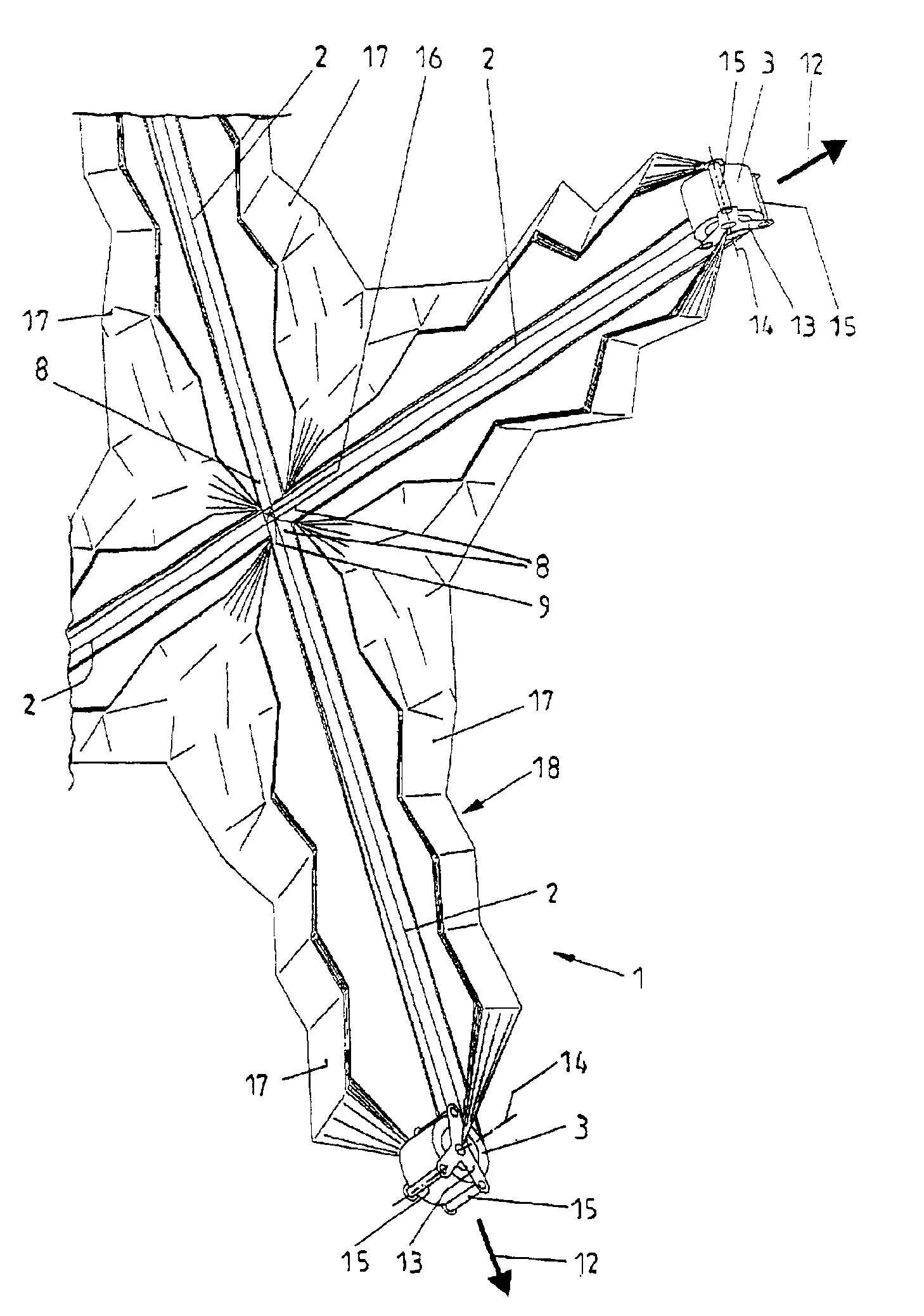
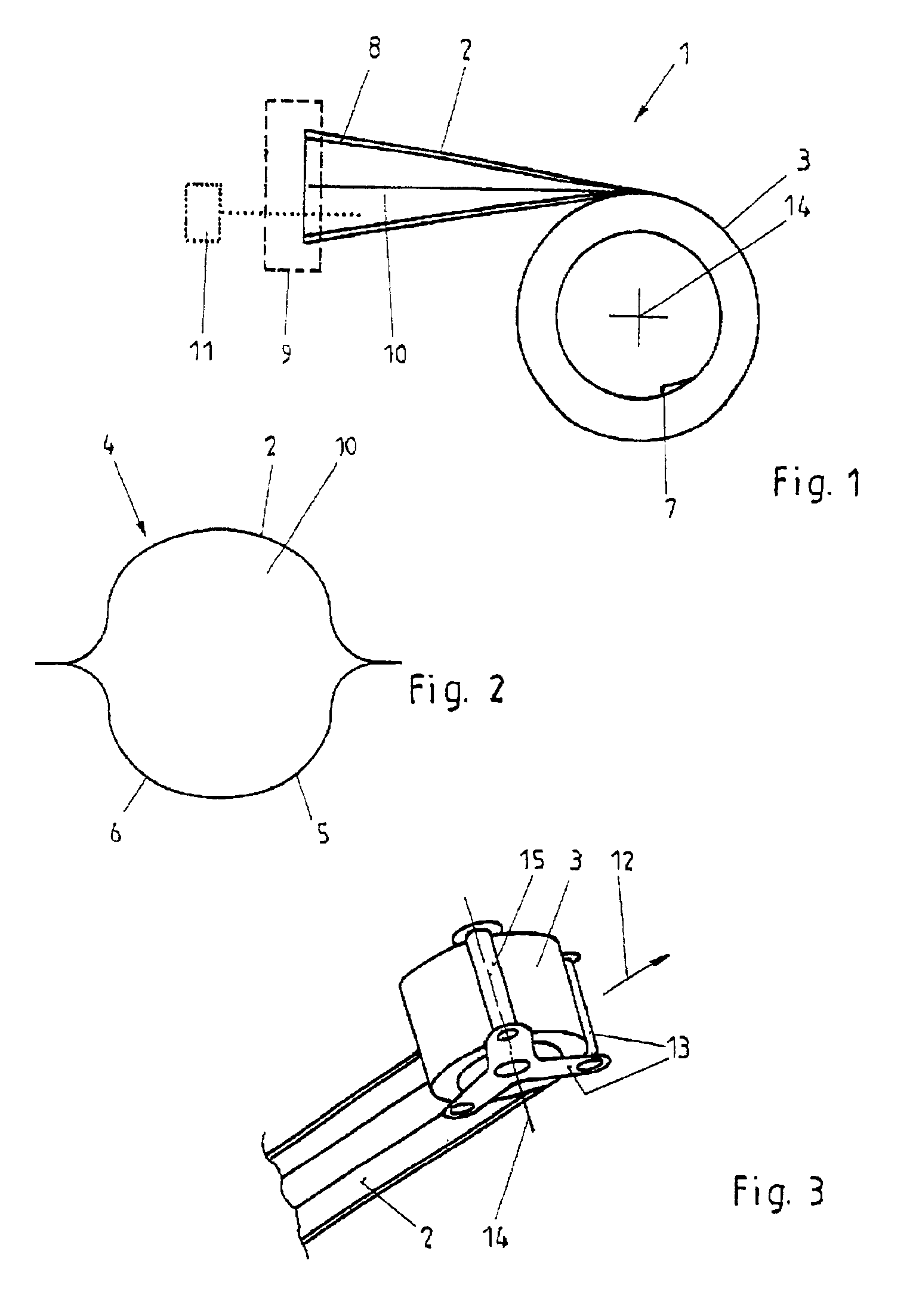
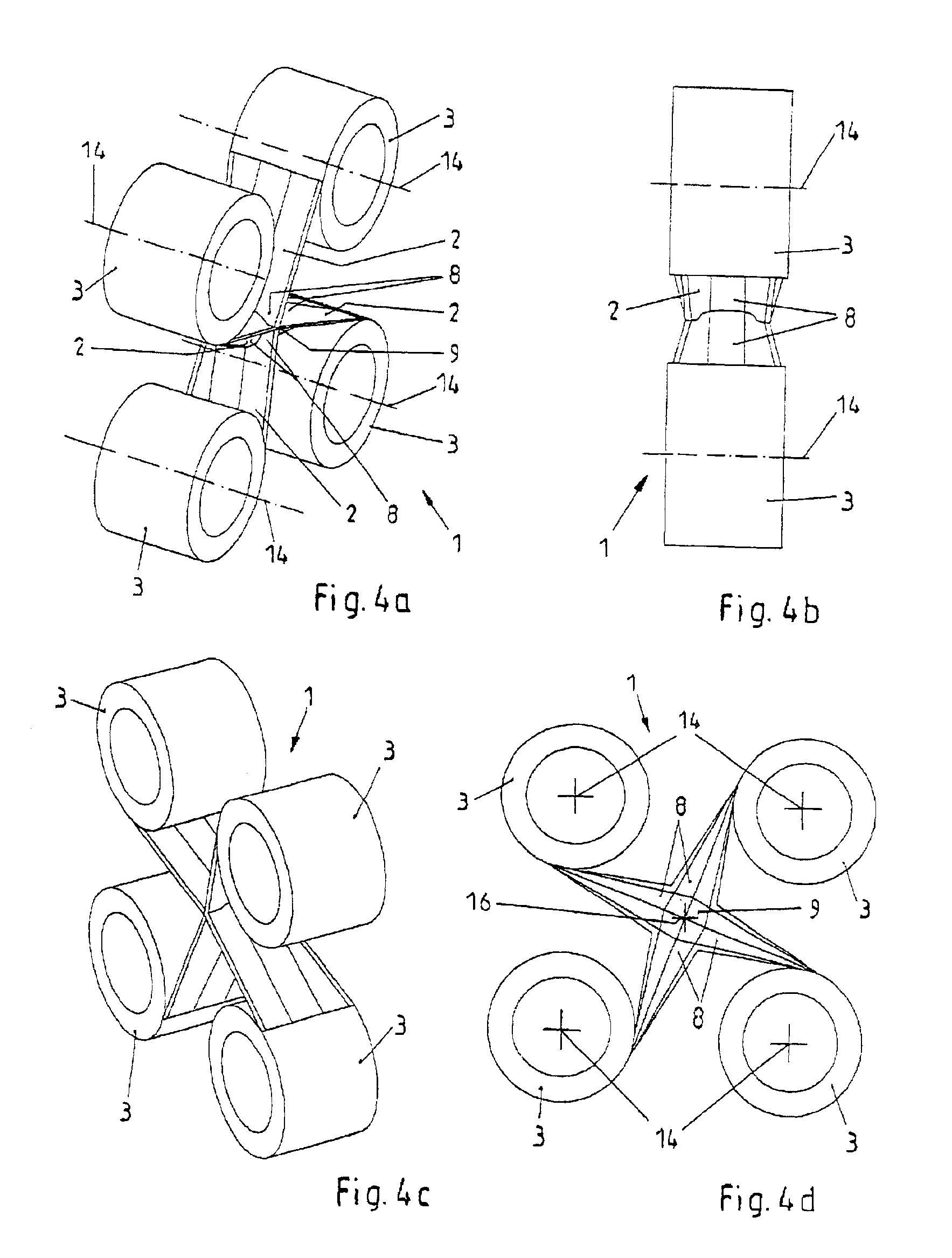
Referring now in greater detail to the drawings, FIG. 1 illustrates an apparatus 1 including a boom 2 (or a mast or a pole) being wound up over most of its length to form a roll 3. The boom 2 in its unrolled extended position and in a position in which it is free from forces has the cross section 4 as illustrated in FIG. 4. The boom 2 and its cross section 4, respectively, may be compressed to attain a flat cross section, the boom 2 then no longer being buckle-proof in a way that it may be wound up to form the roll 3. Especially, the boom 2 may be made of carbon fiber composite material 5, or at least the deformable wall 6 of the boom 2 may be made of carbon fiber composite material 5. The boom 2 has a very small mass and a very light weight, respectively, taking its unrolled length and its great stiffness in the unrolled position into account, as it corresponds to the cross section 4.

The novel apparatus 1 as illustrated in FIG. 1 includes the boom 2 being rolled up to form the roll...


PUM


Abstract

An apparatus includes at least one boom including a tip and a foot and being designed and arranged to be rolled up to form a roll. The tip is located in a radial inward region of the roll and the foot being located in a radial outward region of the roll. The apparatus further includes a unit being designed and arranged to unfold the at least one boom and including a bearing being designed and arranged to cooperate with the foot in a way that the boom in the region of the bearing at the beginning of the unfolding process has an enlarged cross section. Especially, the apparatus may be used in space technology for unfolding a solar sail.

Description

CROSS REFERENCE TO RELATED APPLICATIONSThis application claims the benefit of co-pending German Patent Application No. 101 09 529.5-22 entitled “Vorrichtung mit einem im Querschnitt flach zusammengedrückten und der Länge nach aufgerollten Mast”, filed on Feb. 28, 2001.FIELD OF THE INVENTIONThe present invention generally relates to the field of apparatuses including ultralight expandable booms. Such apparatuses include a boom the cross section of which may be compressed and which may be rolled up along its length. More particularly, the present invention relates to an apparatus including a lightweight boom to be rolled up to form a roll and to be connected to a solar sail or the like.BACKGROUND OF THE INVENTIONTypically, the apparatuses include booms made of carbon fiber composite material. For example, such apparatuses are used in space technology, for example to span solar sails. It is desired that these apparatuses have a low mass or weight, respectively, and that they may be tra...

Claims


Application Information

Patent Timeline
IPC IPC(8): B64G1/22B64G1/40
CPCB64G1/222B64G1/407
Inventor BREITBACH, ELMARSICKINGER, CHRISTOPHHERBECK, LARS
Owner DEUTSCHES ZENTRUM FUER LUFT & RAUMFAHRT EV
Why Eureka
Try Eureka