Cylinder to cylinder balancing using intake valve actuation

a technology of intake valve and cylinder, which is applied in the direction of electric control, machines/engines, output power, etc., can solve the problems of difficult to achieve the goal, lack of uniform combustion characteristics from cylinder to cylinder, and increased difficulty in achieving the goal

a technology of intake valve and cylinder, which is applied in the direction of electric control, machines/engines, output power, etc., can solve the problems of difficult to achieve the goal, lack of uniform combustion characteristics from cylinder to cylinder, and increased difficulty in achieving the goal

US6843231B1Active Publication Date: 2005-01-18CATERPILLAR INC

Image

  • Cylinder to cylinder balancing using intake valve actuation
  • Cylinder to cylinder balancing using intake valve actuation
  • Cylinder to cylinder balancing using intake valve actuation

Examples


Embodiment Construction

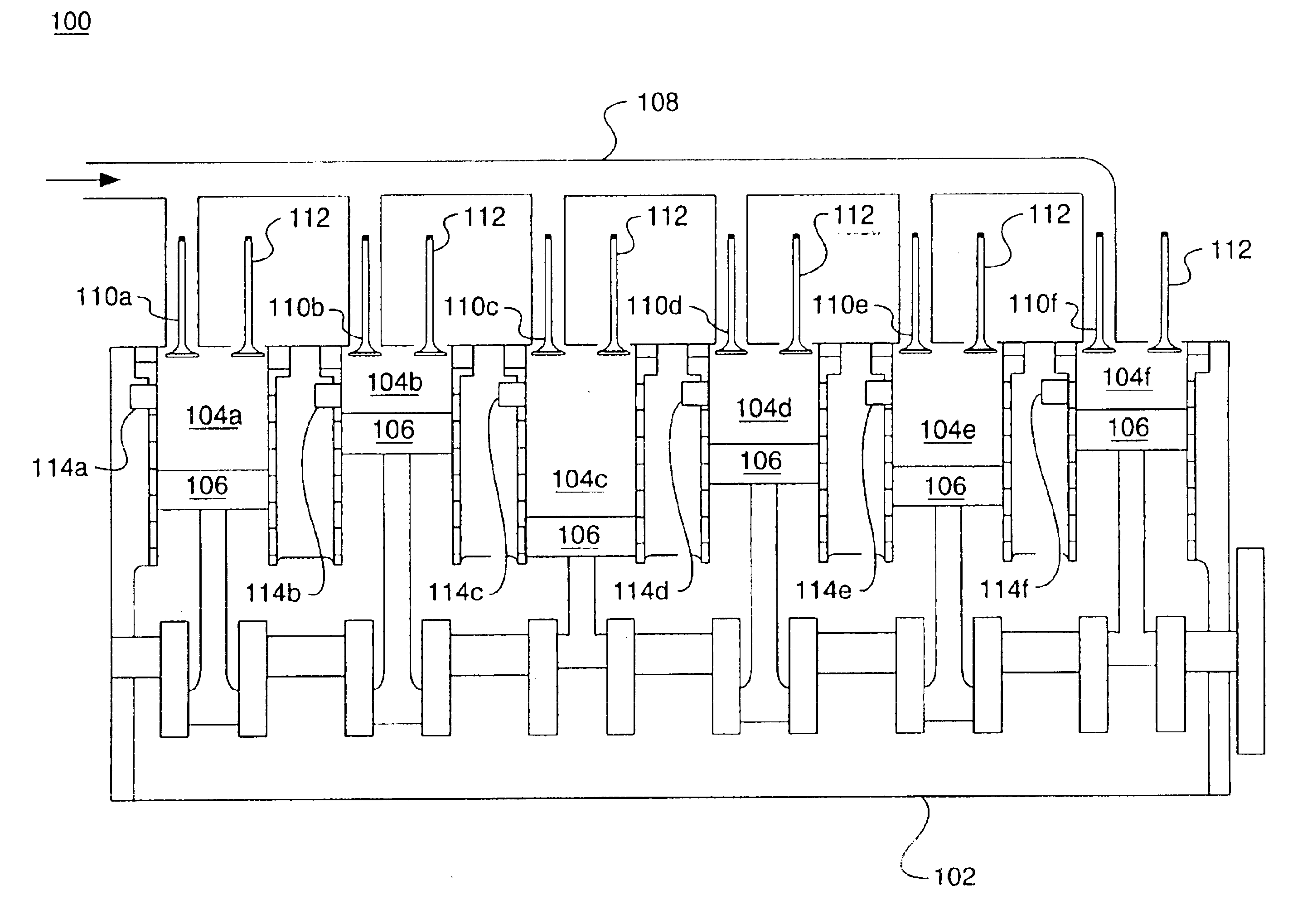
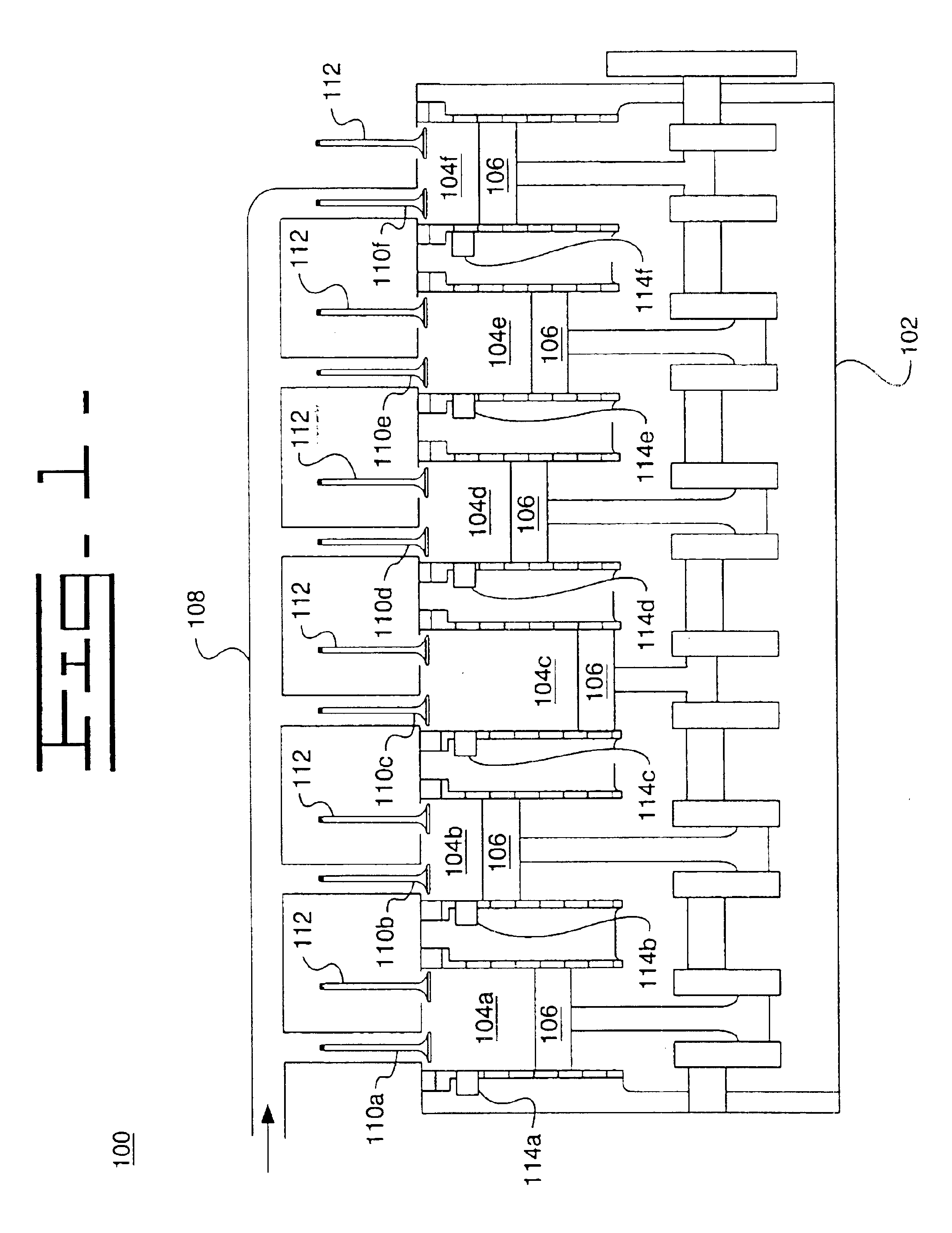
Referring to the drawings, a method and apparatus 100 for adjusting a combustion timing of cylinders 104 in an engine 102 is shown. More specifically, a method and apparatus 100 for balancing a combustion phasing between a plurality of cylinders 104 located in an engine 102 is shown.

Referring to FIG. 1, a diagrammatic illustration of an engine 102, i.e., an internal combustion engine, is shown. The engine 102 includes a number of combustion cylinders 104, within which a corresponding number of pistons 106 are located which slidably move in the cylinders 104, as is well known in the art. FIG. 1 depicts six (6) cylinders 104a,b,c,d,e,f. However, the engine 102 may have any number of cylinders 104 for operation.

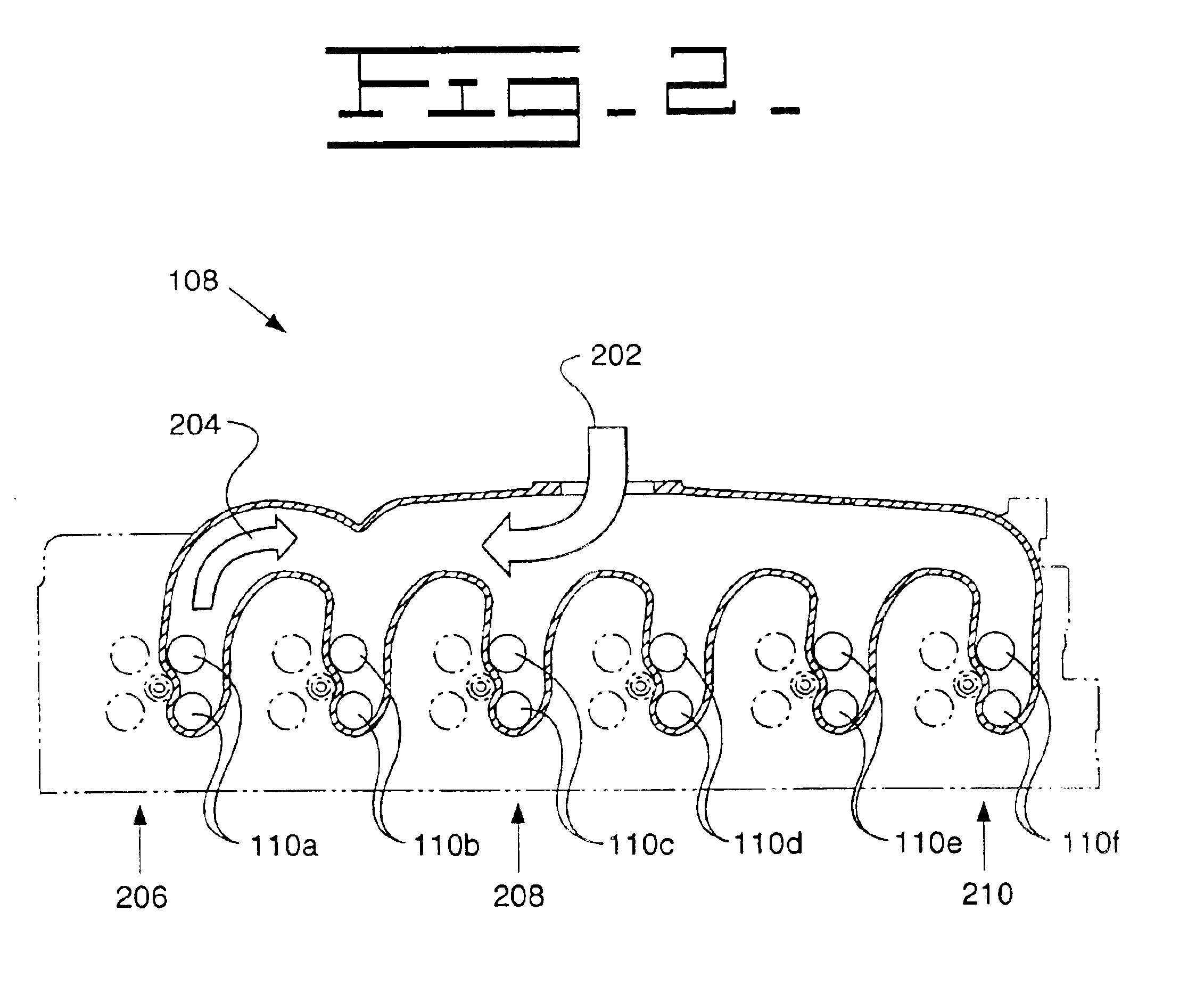
An intake manifold 108 connects to each cylinder 104 and provides a path for an intake fluid, such as fresh air, into each cylinder 104. Fluid communication of the air is controlled per cylinder by intake valves 110. For example, the engine 102 of FIG. 1 has six (6) intake valve...


PUM


Abstract

A method and apparatus for balancing a combustion phasing between a plurality of cylinders located in an engine. The method and apparatus includes a determining a combustion timing in each cylinder, establishing a baseline parameter for a desired combustion timing, and varying actuation of at least one of a plurality of intake valves, each intake valve being in fluid communication with a corresponding cylinder, such that the combustion timing in each cylinder is substantially equal to the desired combustion timing.

Description

TECHNICAL FIELDThis invention relates generally to a method and apparatus for balancing the combustion process in individual cylinders in an internal combustion engine and, more particularly, to a method and apparatus for cylinder to cylinder balancing using variable intake valve actuation for each cylinder.BACKGROUNDIt has long been desired to operate internal combustion engines, in particular engines with multiple combustion cylinders, in a manner which results in optimal performance with minimal emissions. This goal, however, is difficult to achieve. One contributing factor is the lack of uniform combustion characteristics from cylinder to cylinder. Variables such as air mass, temperature and pressure imbalances contribute to this non-uniformity. The problem may be made worse by the use of intake valve actuation techniques, such as Miller cycle, which may induce a backflow of air from cylinders into input ports. The result may include differences in peak cylinder pressure, rise r...

Claims


Application Information

Patent Timeline
18 Jan 2005
Publication
US6843231B1
IPC
F02D19/10; F02D35/02; F02D41/00; F02D19/00; F02D19/06; F02B29/04; F02D13/02; F02B29/00; F02D41/34; F02B1/12; F02D41/30; F02B1/00; F02M25/07
CPC
F02B29/0493; F02D13/0234; F02D35/023; F02D35/028; F02D41/0002; F02D41/0085; F02D41/3035; F02B29/0418
Inventors
DUFFY, KEVIN P.; KIESER, ANDREW J.