Partially closed microfluidic system and microfluidic driving method

a microfluidic system and driving method technology, applied in the direction of positive displacement liquid engine, fluid coupling, laboratory glassware, etc., can solve the problems of inability to meet the need for two-way driving, different limitations of non-mechanic pumps, and higher cost of this kind of manufacturing process, so as to achieve the effect of extending the fluid flowing distance and conquering the distance limitation in pushing the fluid

Inactive Publication Date: 2005-01-18
IND TECH RES INST
View PDF7 Cites 45 Cited by
  • Summary
  • Abstract
  • Description
  • Claims
  • Application Information

AI Technical Summary

Benefits of technology

The embodiment with more than one deformable chamber can readily conquer the distance limitation in pushing the fluid. The deformable chambers can be connected in series or parallel in order to extend the fluid flowing distance.

Problems solved by technology

Generally speaking, mechanic pumps only provide one-way driving and, therefore, often cannot satisfy the need for two-way driving.
Non-mechanic pumps have different limitations, depending upon different designs.
Since the cost of this kind of manufacturing process is higher, it is not ideal to be implemented on dispensable chips with limited functions.

Method used


Image

  • Partially closed microfluidic system and microfluidic driving method
  • Partially closed microfluidic system and microfluidic driving method
  • Partially closed microfluidic system and microfluidic driving method

Examples


Embodiment Construction

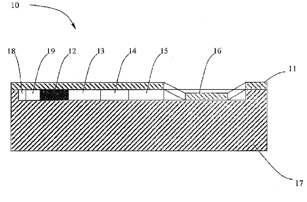
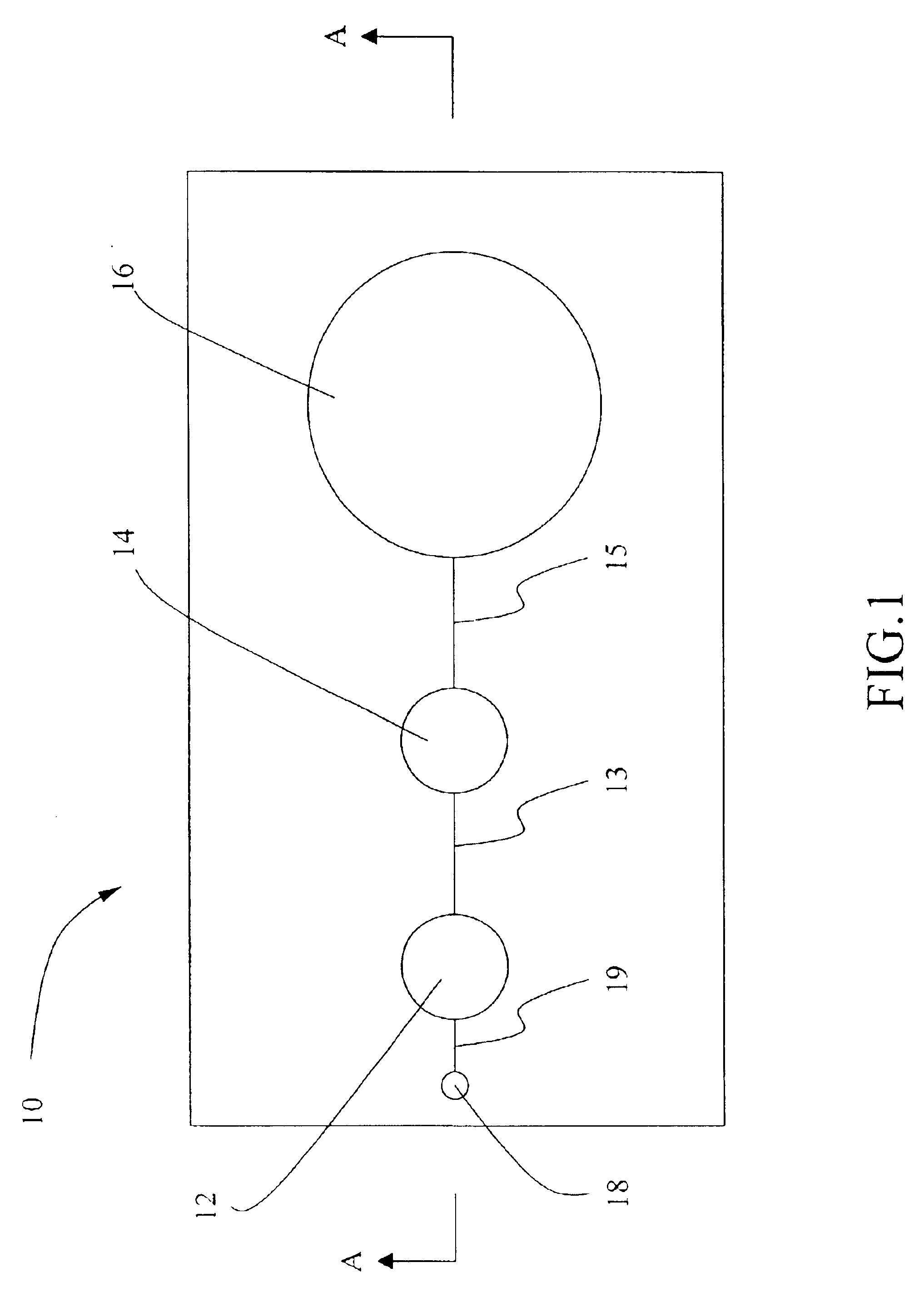
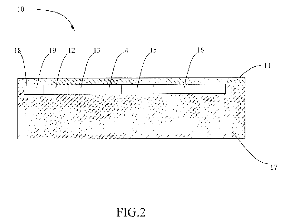
The invention provides one or several deformable chambers inside a micro fluid system so that the fluid can be driven to flow by imposing a pressure on the deformable chambers. That is, an elastic deformable thin film is attached on the substrate of a micro fluid chip to form a partially closed micro fluid system. The so-called partially closed micro fluid chip does not have any hole or channel connecting to its ambient space except for a vent hole when in operation.

In addition to necessary microfluidic elements, the chip is also provided with one or several deformable chambers that are connected in series or independent of one another. The deformable chambers are connected to the microfluidic elements on the chip through micro channels. The deformable chambers and the microfluidic elements are connected by micro channels, forming the microfluidic system for the micro fluid. A fine-tunable actuator is provided at each deformable chamber. The microfluidic movement on the chip is made...


PUM


Abstract

This specification disclosed a partially closed microfluidic system and a fluid driving method. The microfluidic system is comprised of a substrate with microfluidic elements and a thin film. A feature of this structure is that the thin film is elastic and deformable. It has a single opening corresponding to a vent hole on the substrate, thus forming a partially closed microfluidic system. The substrate is designed to have several positions for micro fluid elements and deformable chambers and uses micro channels to form a complete network. Since the thin film is elastic and deformable, one is able to impose a pressure on the thin film above the deformable chambers in this partially closed microfluidic system to drive the fluid into motion. Once the pressure is released, the fluid flows back to its original configuration.

Description

BACKGROUND OF THE INVENTION1. Field of InventionThe invention pertains to a microfluidic system on chips and, in particular, to a partially closed microfluidic system in which the fluid makes a reciprocal motion and a corresponding fluid driving method.2. Related ArtPump systems are commonly used in driving fluid. In addition to the uses of external pumps, chips also employ internal driving methods. These built-in driving means can be classified as mechanic micropumps and non-mechanic micropumps. In particular, the mechanic micropump technique includes the reciprocating-diaphragm and peristaltic types.Most existing micropumps belong to the reciprocating-diaphragm type. This type of micropumps generally has a structure comprised of a pump body, an actuator, and a check valve. Commonly used actuators are piezoelectric, electrostatic, and thermopneumatic. Examples of non-mechanic micropumps include bubble pumps, diffuser pumps, electrohydrodynamic pumps (EHD), injection type EHD pumps,...

Claims


Application Information

Patent Timeline
Patent Type & Authority Patents(United States)
IPC IPC(8): F04B43/02F04B43/04B01L3/00
CPCF04B43/043F04B43/02B01L3/5027Y10T137/2213Y10T137/2224Y10T137/0396
Inventor KUO, YUAN-FONGYAO, NAN-KUANGWU, JHY-WENSHIA, TIMPARNG, SHAW-HWA
Owner IND TECH RES INST
Why Eureka
Try Eureka