
Flexible connection between sports device and shoe

a flexible connection technology for sports devices and shoes, applied in the direction of sports equipment, skates, apparel, etc., can solve the problems of parts used, difficult to switch the articulated binding, and easy impairment of correct operation, so as to enhance the performance of users

Inactive Publication Date: 2005-01-18
ATOMIC AUSTRIA
View PDF16 Cites 11 Cited by
  • Summary
  • Abstract
  • Description
  • Claims
  • Application Information

AI Technical Summary

Benefits of technology

The objective of the present invention is to provide a pivotable binding system between a user's foot and a sports device, which can enhance the performance of a user.
The particular advantage of this design is that relatively few and simple components imitate the natural rolling action of the foot across the bottom of the toes so that the performance of every user can be enhanced. Surprisingly, however, the enhanced performance which can be achieved by using the design proposed by the invention is not accompanied by any impairment to comfort. On the contrary, comfort is perceptibly increased due to the harmonious or rounded movement of the binding system. The combined or largely rigidly coupled motion of the user's foot in translation and rotation relative to the sports device during the active phase of the binding system. i.e. when assuming a specific pivot position, gives the user a feeling of stability and functional safety. As a result, he can concentrate on the respective performance and does not haveto consciously concentrate his efforts on a perfect rolling motion, since this is pre-programmed by the binding system to a certain degree. Furthermore, the binding system consists of a few individual components, which makes the design optimum in terms of weight whilst nevertheless enabling the advantageous rolling motion in translation and rotation. At the same time, any undesirable movement between the user's foot and the sports device, such as twisting about a vertical axis, can be reliably prevented, thereby producing a high resistance to force. Because of the small number bearing points, friction losses between the linking parts of the binding system can be kept particularly low, so that the user's potential to perform can be largely converted into kinetic energy to propel the sports device along. Another important advantage resides in the fact that the sole of the sport shoe, for example a cross country shoe, can be made to a more bend-resistant design than similar conventional sport shoes because the harmonious or flowing movement needed for an optimum forward propulsion can be produced by the binding device. The natural forward rolling motion across the heels when walking or running is simulated by the binding system proposed by the invention, thereby enhancing comfort when using the sports device. Because the sport shoe can be made relatively more resistant to bending, the driving energy applied by the user can be more effectively converted into forward driving energy, thereby simultaneously enhancing performance without, as one might expect, impairing comfort.
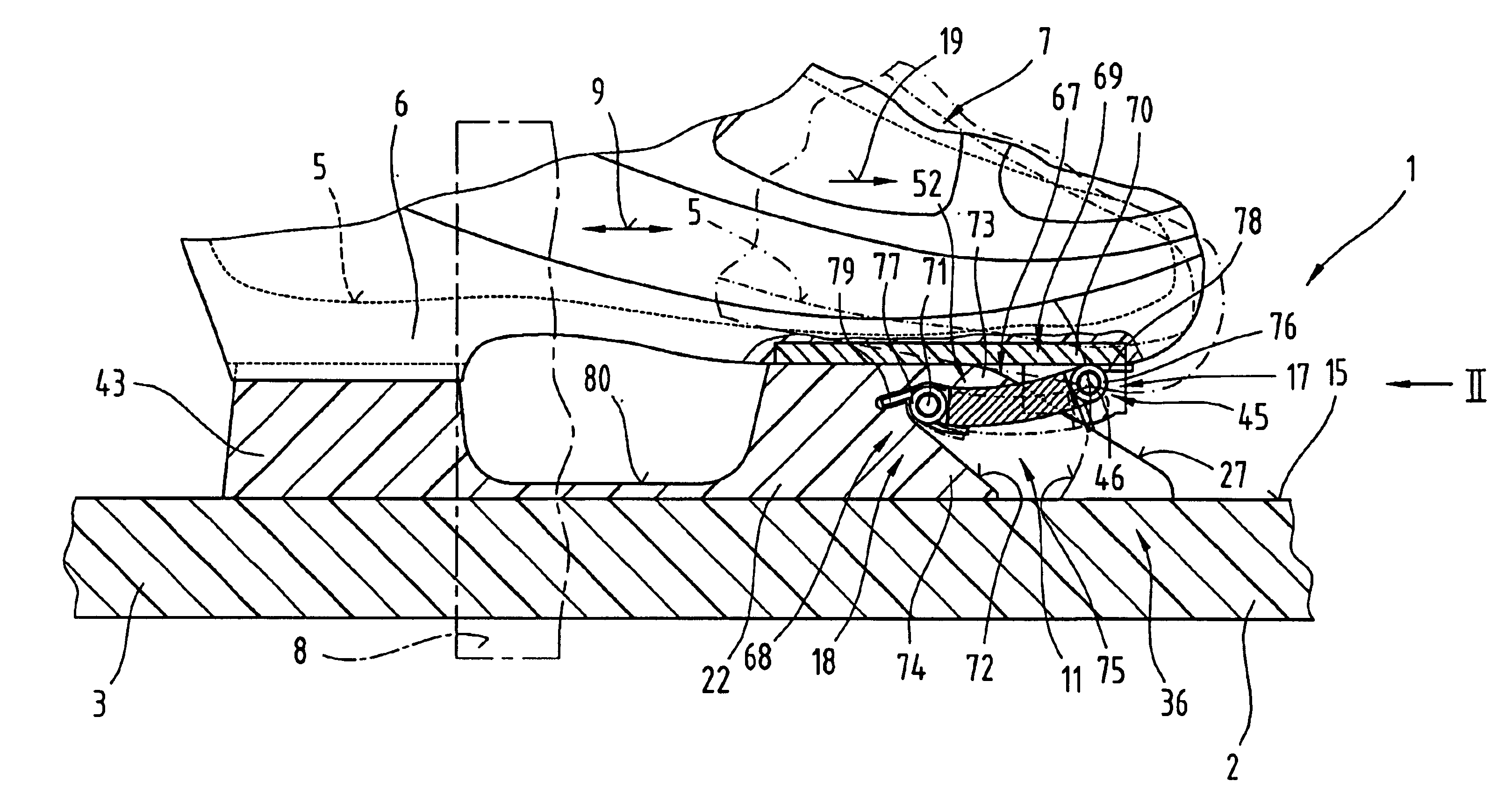
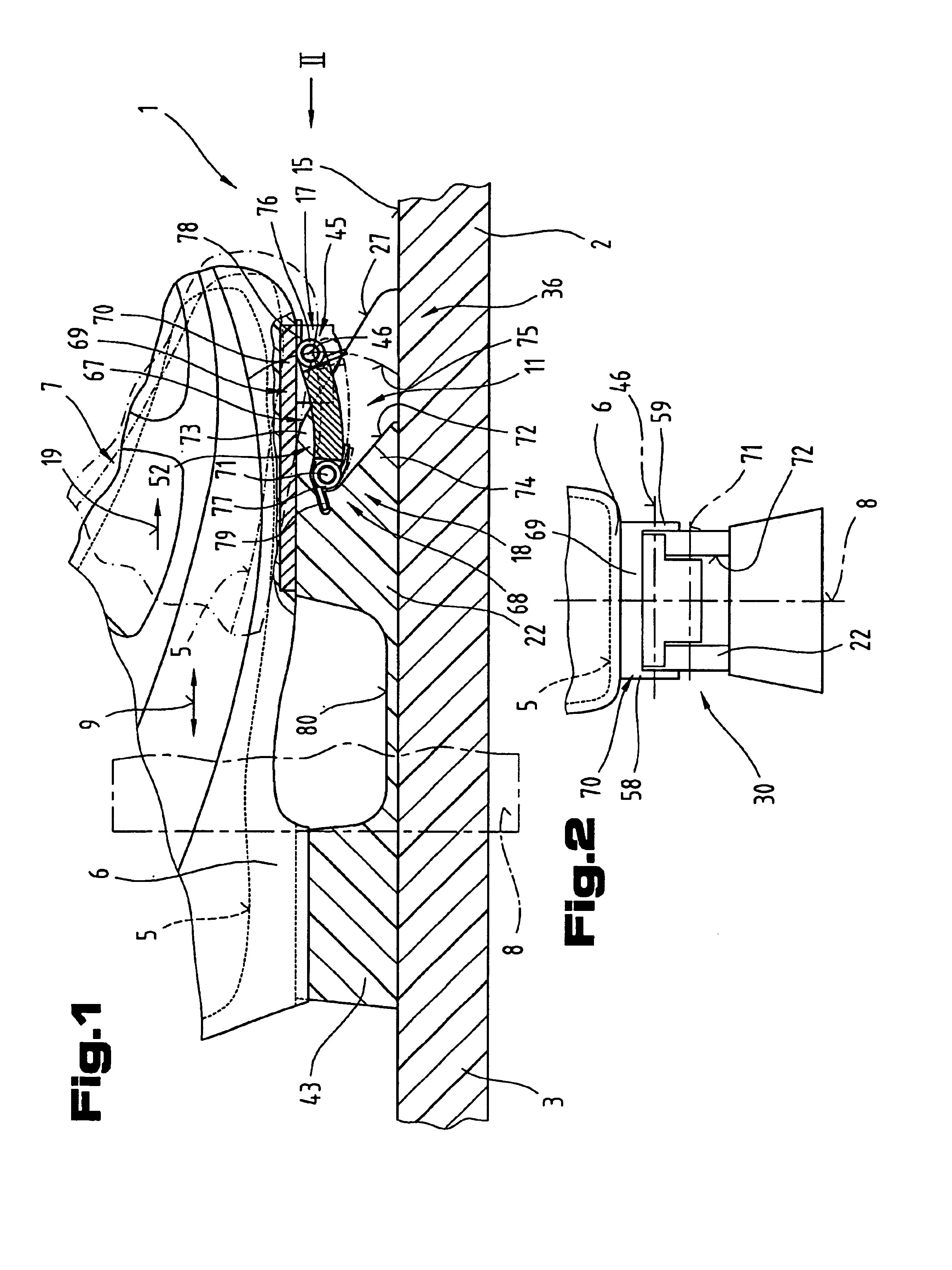
In an advantageous embodiment in which the lever can be accurately guided and is capable of withstanding high forces, the body rollingly supporting the front end of the tread surface defines a recess housing a predominant portion of the lever, and a stop element in the recess restricts the pivoting movement of the lever about the stationary pivot axis. Kinematically detrimental lever positions can also be prevented due to the fact that the pivoting motion is restricted.

Problems solved by technology

The disadvantage of this system is that correct operation can be easily impaired under difficult conditions of use.
The disadvantage of this system is that it is difficult to switch the articulated binding from the active into the locked position and vice versa and the shear forces or twisting forces which occur between the sports device and the user's foot relative to a vertical axis place high demands on the parts used.
Furthermore, when the binding system is in the active position, the central region of the sports device underneath the user's -shoe is placed under a high degree of strain due to the fact that the bearing points are small in surface area or linear in shape.
Another disadvantage is the fact that the front region of the sports device may rise if the user leans backwards.
The disadvantage of this is that the user of this binding system is unable to get a firm hold on the sports device, which reduces performance.
Another disadvantage is that the kickoff which can be achieved with this system is difficult to control and a certain amount of instability in the kickoff is unavoidable, particularly if there is a change in ground conditions.

Method used


Image

  • Flexible connection between sports device and shoe
  • Flexible connection between sports device and shoe

Examples


Embodiment Construction

FIGS. 1 and 2 illustrate one embodiment of a binding system 1 as proposed by the invention, between a sports device 2 in the form of a sliding or rolling member 3, such as a ski 4 or a roller-skate for example, and a tread surface 5 for a user's foot. The tread surface 5 for the user's foot is preferably a shoe sole 6 of a sport shoe 7.

Alternatively, the tread surface 5 for the user's foot may also be a separate, contoured, largely non-deformable bearing element, designed to support or releasably receive the sport shoe 7.

The binding system I can be used with a whole variety of sports devices 2. In particular, the binding system I is suitable for joining appropriate sport shoes 7 to skis for cross-country skiing or touring sports. Similarly, the binding system 1 may be used with ice skating boots and / or with single or multi-track roller-skates. This being the case, the term sports device 2 should be read as meaning a skating blade or single- or multi-track rollers or a retaining fram...


PUM


Abstract

The invention describes a pivotable binding system (1) for mounting between a sports device (2) and a tread surface (5) for a user's foot, in which the tread surface (5) is pivotable about an axis extending more or less parallel with the ankle joint of the foot and is displaceable, at least in a part region assigned to the toes, to a position closer to the sports device (2), and can be joined to the sports device by at least one binding element (11). The binding element (11) is flexible and is resiliently deformable in a vertical plane (8).

Description

BACKGROUND OF THE INVENTION1. Field of the InventionThe invention relates to a pivotable binding system between a sports device and a tread surface for a user's foot.2. Description of the Prior ArtWO 96 / 37269 A1 discloses a device for binding a shoe to a sports device. This device comprises a top part frame, which can be connected to a user's shoe, and pivotably connected to a bottom part frame by means of a hinge mechanism comprising a plurality of linking arms and joints designed to be fixed to various sports devices. The linking mechanism connecting the top to the bottom part frame is constructed so that a pivoting movement of the top part frame relative to the bottom part frame simultaneously causes the two part frames to slide relative to one another. Return spring means are additionally provided which elastically push the two part frames against one another into a predefined relative position. The disadvantage of this system is that correct operation can be easily impaired und...

Claims


Application Information

Patent Timeline
IPC IPC(8): A63C9/00A63C1/00A63C1/28A43B5/04
CPCA43B5/0417A63C9/00A63C1/28A43B5/0496
Inventor RIEPLER, BERNHARD
Owner ATOMIC AUSTRIA
Learn More