Pipe coupling device

a technology of coupling device and pipe, which is applied in the direction of hose connection, sleeve/socket joint, mechanical apparatus, etc., can solve the problem that the gripping force is not significantly further enhanced by the angl

Inactive Publication Date: 2005-01-18
CRANE CO
View PDF15 Cites 52 Cited by
  • Summary
  • Abstract
  • Description
  • Claims
  • Application Information

AI Technical Summary

Benefits of technology

is to provide a pipe coupling in which a firm gripping force can be applied to a pipe over a

Problems solved by technology

One problem confronting manufacturers of pipe couplings is that for pipes having a given nominal outside diameter (O.D.), the pipes in practice may have O.D.s varying over quite a wide range.
To overcome this problem, the taper of the supp

Method used


Image

  • Pipe coupling device
  • Pipe coupling device
  • Pipe coupling device

Examples


Embodiment Construction

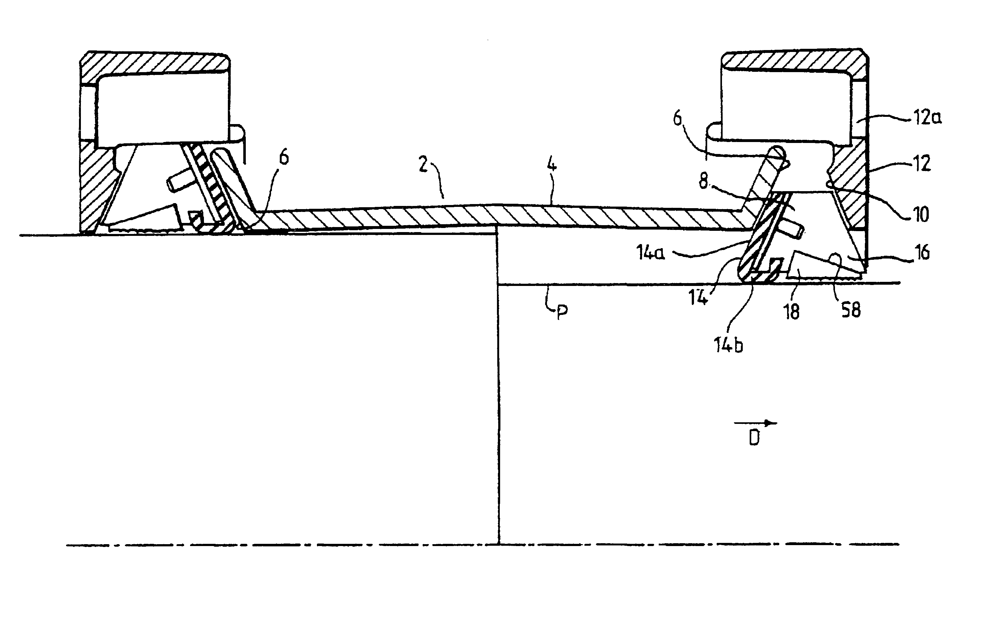
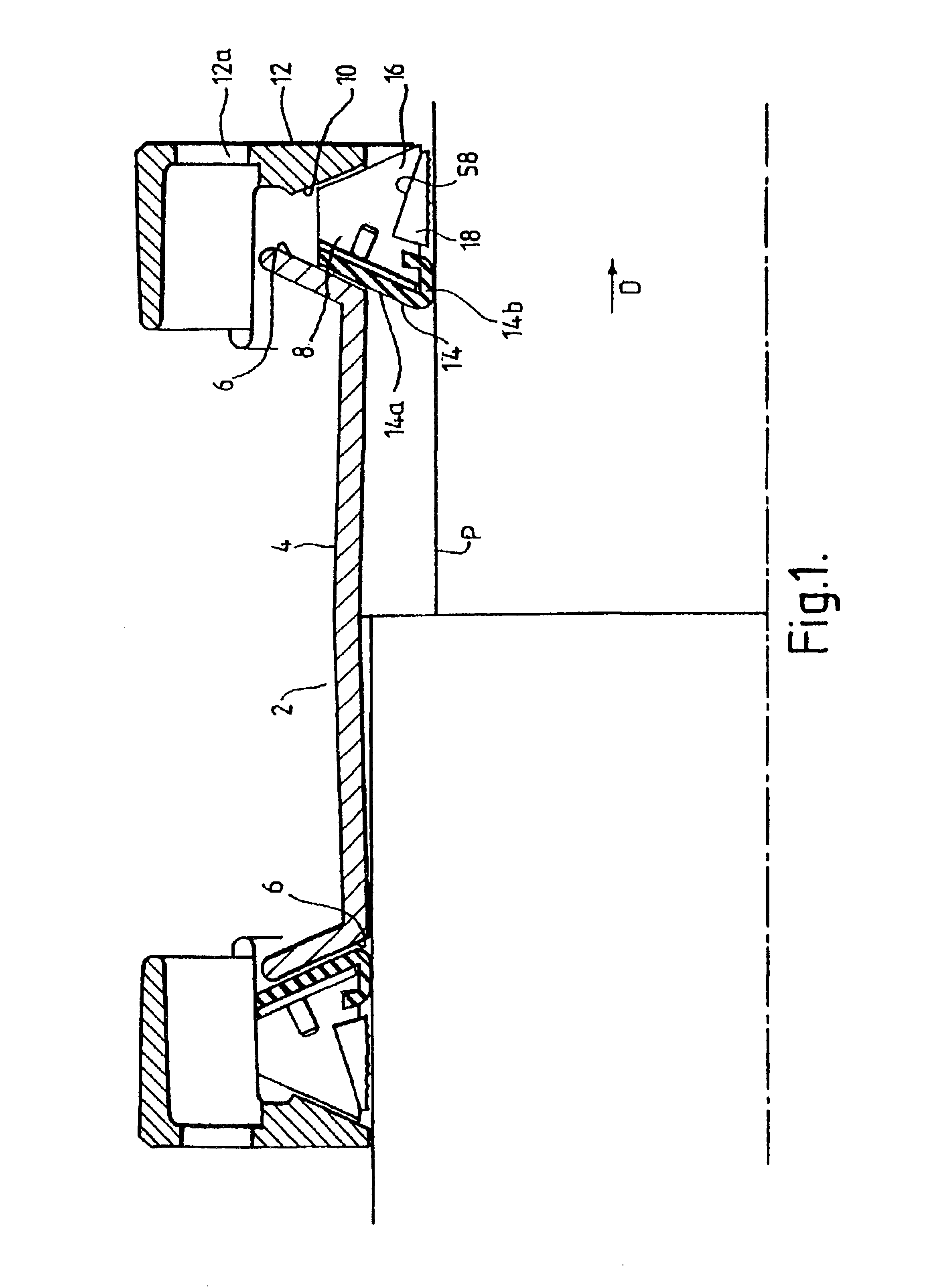
Referring now to the drawings, a pipe coupling device 2 according to one embodiment of the present invention includes a generally cylindrical sleeve 4, which in this embodiment has been cast from ductile iron, although it could alternatively be fabricated from steel, for example by forming a cylindrical blank from a blank strip and then deforming the cylindrical blank to the desired shape.

At each end, the sleeve 4 is provided with an inclined annular first abutment surface 6. A sealing and gripping assembly 8 is situated between the first abutment surface 6 and a second abutment surface 10 of a compression flange 12. Flange bolts (not shown) pass through apertures 12a in the compression flanges and provide a means of drawings the compression flanges together.

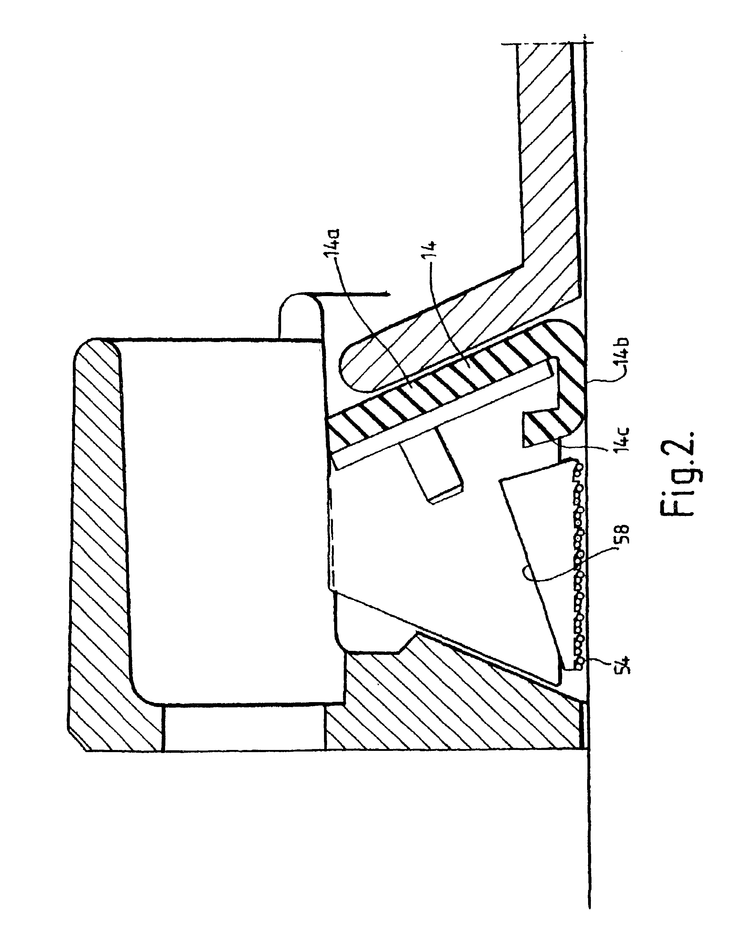
The sealing and gripping assembly 8 comprises a gasket 14 formed from a suitable elastomeric material, an annular member 16 (corresponding to the “annular carrier” of the claims) and a gripping member 18. The annular member 16 (...


PUM


Abstract

A pipe coupling device (2) for joining the ends of two pipes is disclosed. The pipe coupling device (2) includes a sleeve (4) configured to receive an end of a pipe and having an annular first abutment surface (6); a compression member (12) having an annular second abutment surface (10); a sealing and gripping assembly (8) for sealing against and gripping the pipe; and threaded fasteners for drawing the compression member (12) and the sleeve (4) axially together so as to compress the sealing and gripping assembly (8) against the pipe. The sealing and gripping assembly (8) includes a sealing member (14) and a gripping device. The gripping device may include an annular carrier (16) having an annular recess for retaining a gripping member (18). The gripping surface of the gripping member (18) and the annular carrier (16) are adapted for relative axial movement wherein the gripping member (18) may be moved into tighter contact with the pipe.

Description

FIELD OF THE INVENTIONThe present invention relates to a device for coupling to a pipe. In particular, the invention relates to a pipe coupling device which grips and seals pipes with a range of outer diameters.BACKGROUND OF THE INVENTIONThe expression “pipe” as used herein is intended to include pipes and tubes as such, and also pipe-like members and fittings for use in pipework such as bends, elbows, “T” connectors, flange adaptors and parts and devices adapted to be fitted to pipework such as valves and pumps. Such pipes may have a variety offend configurations, and will be plain-ended in contrast to flange-ended.Pipe coupling devices commonly comprise an annular coupling sleeve that can connect with a plain-ended pipe. The connection can be made via a sealing or gripping member such as a sealing gasket arranged about the plain-ended pipe, and an annular compression member disposed about the end of the sleeve and arranged to be drawn axially against the sealing or gripping member...

Claims


Application Information

Patent Timeline
IPC IPC(8): F16L21/02F16L21/04F16J15/10
CPCF16L21/04F16L25/14F16L21/08
Inventor REX, BRIANBEEVOR, MARK ADRIAN
Owner CRANE CO
Why Eureka
Try Eureka