Energy absorbing system

a technology of energy absorption and energy, applied in the direction of transportation and packaging, applications, roads, etc., can solve the problems of increasing the average speed of trains and vehicles, increasing the number of vehicles, and the inability of vehicles to cross and traditional systems for preventing vehicles from crossing the tracks at the inopportune time have not been fully satisfactory

Inactive Publication Date: 2005-01-18
GLOBAL GRAB TECH INC
View PDF23 Cites 87 Cited by
  • Summary
  • Abstract
  • Description
  • Claims
  • Application Information

AI Technical Summary

Benefits of technology

In yet another aspect, a railroad crossing safety system according to the present invention includes a roadway, railroad tracks crossing the roadway, first and second energy absorbing systems installed respectively on each side of the roadway, ground retractable restraining means for restraining automobiles from crossing the railroad tracks, the restraining means extending across the roadway between the first and second energy absorbing systems on each side of the railroad tracks, each of the first and second energy absorbing systems comprising supporting means for providing a rigid support for a fixing means, fixing means for rigidly fixing a vertical axis relative to the supporting means, shock absorbing means for absorbing forces applied to the shock absorbing system, the shock absorbing means being mounted on the fixing means to rotate around the vertical axis, and a threshold force securing mechanism connected to the shock absorber preventing expansion of the shock absorber until acted upon by tensile forces of at least a minimum threshold force, wherein the restraining means comprises horseshoe cable.

Problems solved by technology

The problem of vehicles improperly crossing railroad tracks is becoming more pronounced due to a rise in both the average speed of trains and in the number of vehicles on the roads.
Traditional systems for preventing vehicles from crossing the tracks at inopportune times have proved less than fully satisfactory.
Other vehicle barriers have been proposed, but none have solved the problem in a manner that is both feasible and commercially practical.

Method used


Image

  • Energy absorbing system
  • Energy absorbing system
  • Energy absorbing system

Examples


example

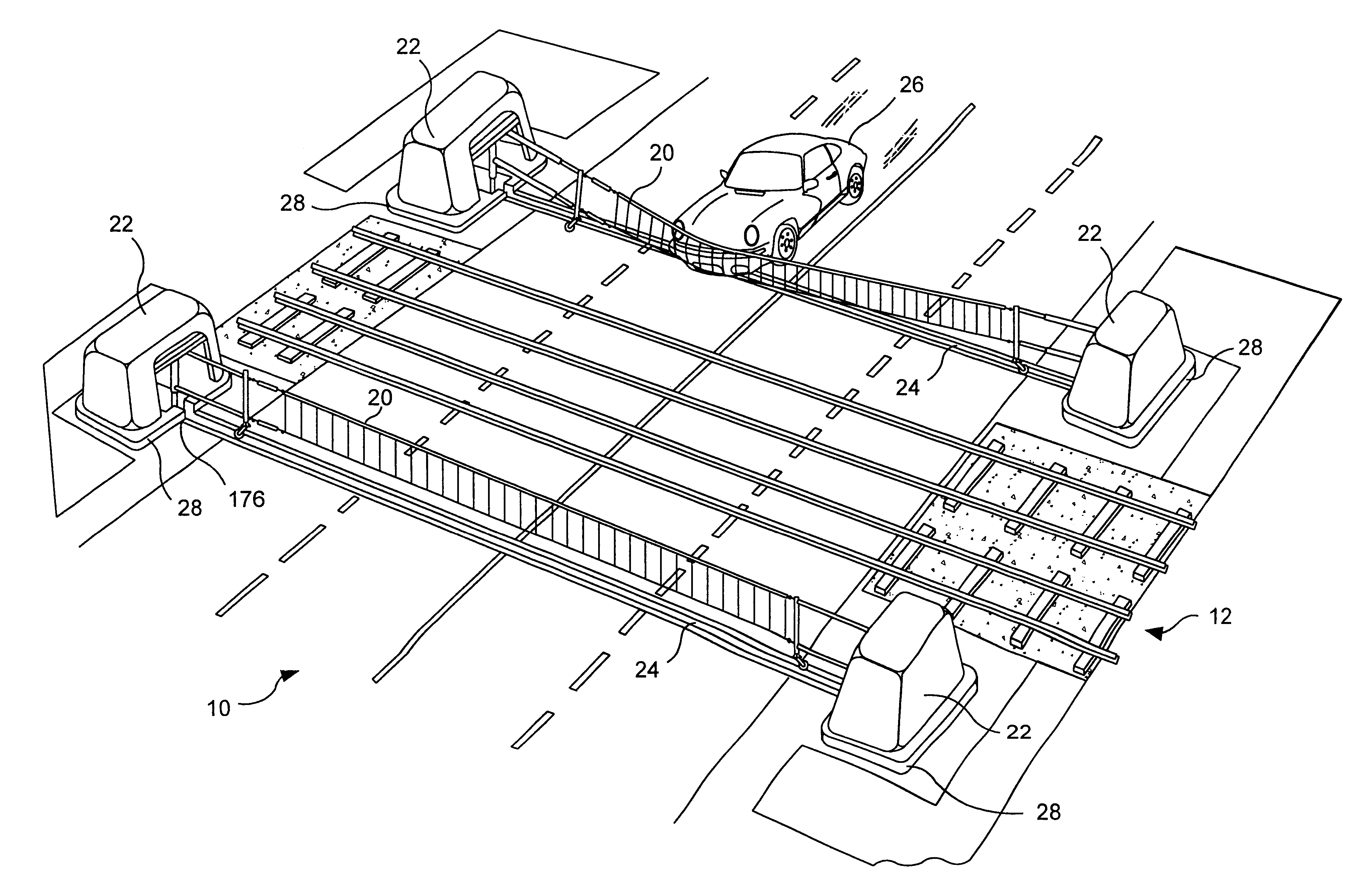
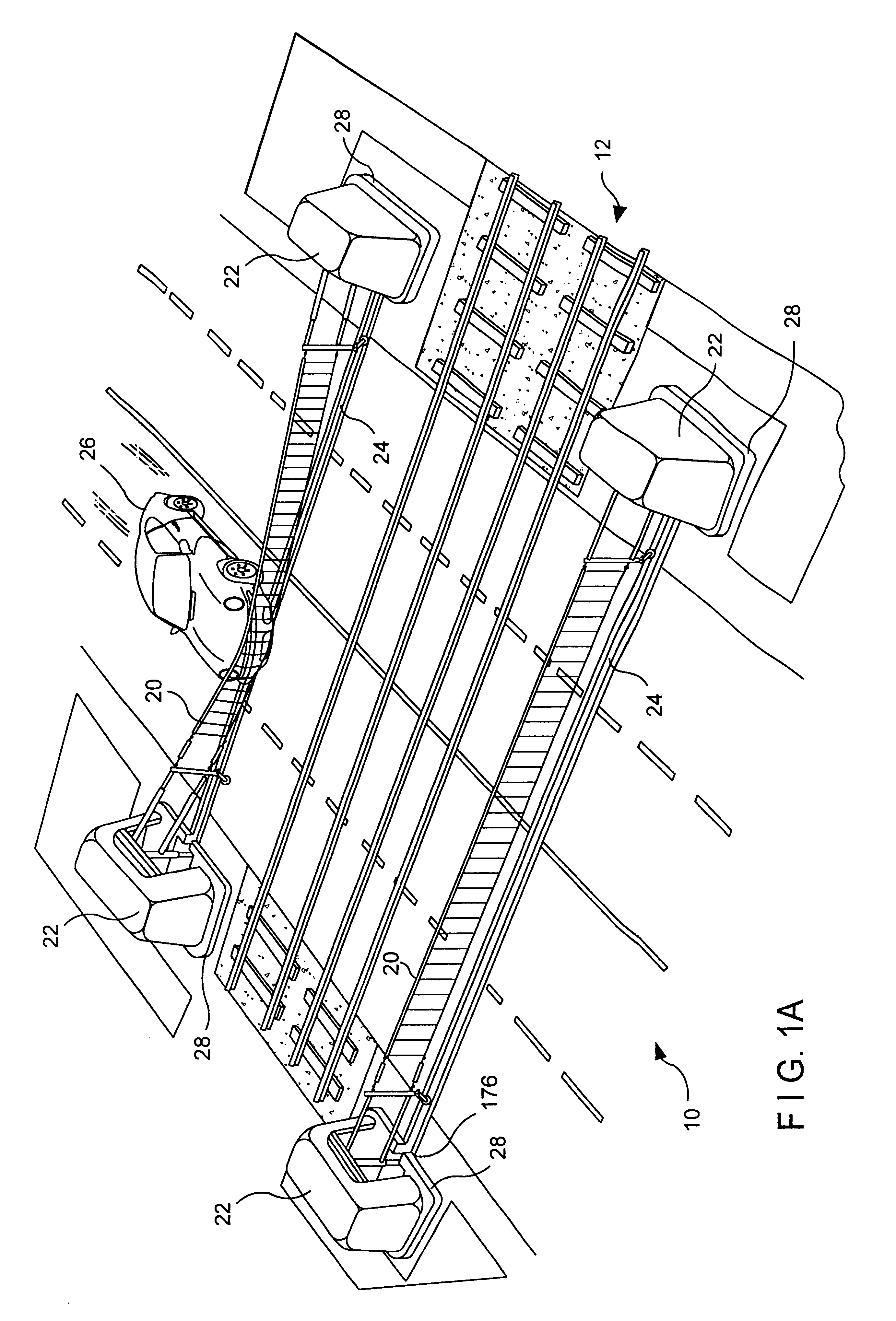
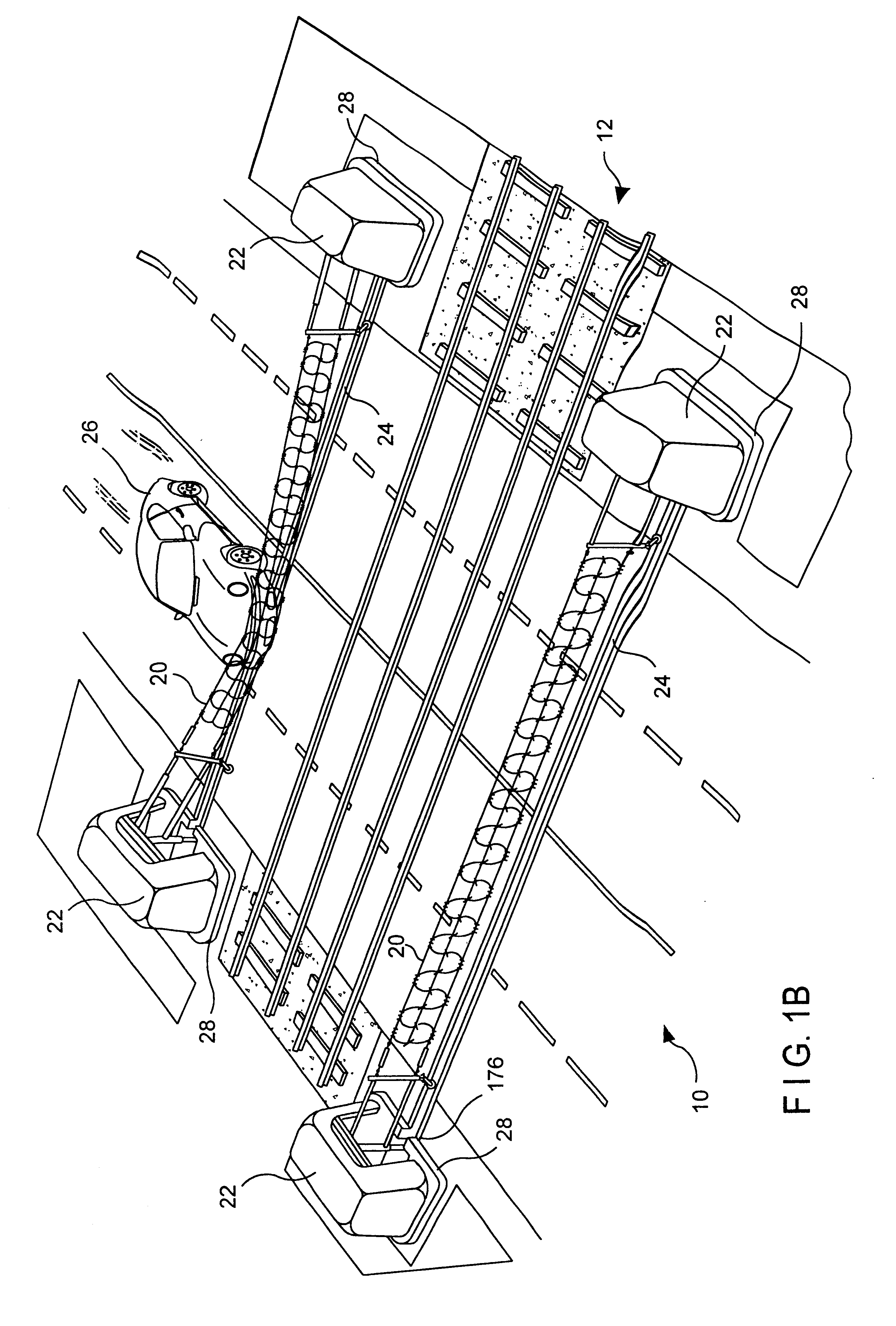
An embodiment similar to that shown in FIGS. 3A and 3B was constructed without ground retractability, as follows. The overall width of the installation was 18.4 m (60.4 ft) centerline to centerline of the stanchions. The net width was 10.5 m (34.5 ft). The uninstalled constructed net height was 0.9 m (3.0 ft). The height of the net when installed and tensioned was 1.0 m (3.3 ft) to the center of the top cable and 0.2 m (0.7 ft) to the center of the bottom cable as measured at the centerline of the net assembly. A measure of the tension was recorded in the top and bottom cables of 27.5 kN (6182.3 lb) and 17.5 kN (3934.2 lb), respectively.

The cable net was constructed of three equally spaced horizontal members. The top and bottom horizontals were 19 mm (0.8 in) diameter Extra High Strength (EHS) wire strand. The center horizontal was 16 mm diameter 6×26 wire rope. The horseshoe cable net members were fabricated of a single 16 mm (0.6 in) diameter 6×26 wire rope. The wire rope was wove...


PUM


Abstract

A heavy duty ground retractable automobile barrier for a railroad crossing. Concrete bunkers are placed at each side of a roadway. An upstanding concrete-filled steel pipe fixed in each bunker has a sleeve for rotational and axial movement. Shock absorbers are mounted on each sleeve. A net extends across the road and is attached to the opposite ends of the shock absorbers. Collision of an automobile with the net creates tensile forces in the net. The shock absorbers expand while rotating about the pipe's axis in response to tensile forces from the net that meet or exceed a minimum threshold. Forces from the net pass through the axis of the steel pipe. The net is stored in a pit transverse the roadway parallel to the railroad tracks and is raised and lowered as appropriate. The net includes a cable that extends across the road in a wave pattern, having peaks, valleys and midpoints, wherein tangents of the wave midpoints are at least 90 degrees from tangents of the peaks and valleys.

Description

BACKGROUND OF THE INVENTIONThis invention relates to an energy absorbing system that can be used to dissipate unwanted energy such as, e.g., the energy of an errant vehicle. The system can be used in a variety of applications, including HOV lane traffic control, drawbridges, security gates, or crash cushion applications. In one application, the system is used to prevent a vehicle from crossing a railroad track while the warning gates are down or there is a train in the area.The problem of vehicles improperly crossing railroad tracks is becoming more pronounced due to a rise in both the average speed of trains and in the number of vehicles on the roads. For example, a new high speed rail line has recently been put into service on the east coast of the United States, which passes through densely populated areas. Traditional systems for preventing vehicles from crossing the tracks at inopportune times have proved less than fully satisfactory. Traditional gates can be bypassed by impati...

Claims


Application Information

Patent Timeline
Patent Type & Authority Patents(United States)
IPC IPC(8): E01F13/02E01F13/12E01F13/00B61L29/08B61L29/02
CPCB61L29/08E01F13/123E01F13/028E01F13/04
Inventor GELFAND, MATTHEW A.VELLOZZI, JOSEPHPANER, JOHN S.MACKENZIE, NORMAN D.RUAN, SHUBINBULLARD, JR., D. LANCEALBERSON, DEAN C.
Owner GLOBAL GRAB TECH INC
Why Eureka
Try Eureka