Blower

a blower and blower technology, applied in the field of blowers, can solve the problems of rapid fatigue of operators, achieve the effects of non-reduced blowing effect, non-reduced high holding force, and varied volume of partial air stream

Inactive Publication Date: 2005-01-18
ANDREAS STIHL AG & CO KG
View PDF5 Cites 21 Cited by
  • Summary
  • Abstract
  • Description
  • Claims
  • Application Information

AI Technical Summary

Benefits of technology

The partial steam direction of the partial air stream can advantageously be varied. In addition, or alternatively, the volume of the partial air stream can be varied. The magnitude of the force produced by the compensation component is thereby also variable. In particular by varying the volume of the partial air stream, the operator, depending upon the use, can set a lower operator force that is to be applied or a greater blowing effect, in other words, a larger volume stream in the discharge flow direction. The partial air stream can expediently be cut off. As a result, the blower can also be used with a non-reduced blowing effect and non-reduced high holding forces.

Problems solved by technology

In particular, with high-power blowers, great forces are required for this purpose, which can lead to rapid fatigue of the operator.

Method used


Image

  • Blower
  • Blower
  • Blower

Examples


Embodiment Construction

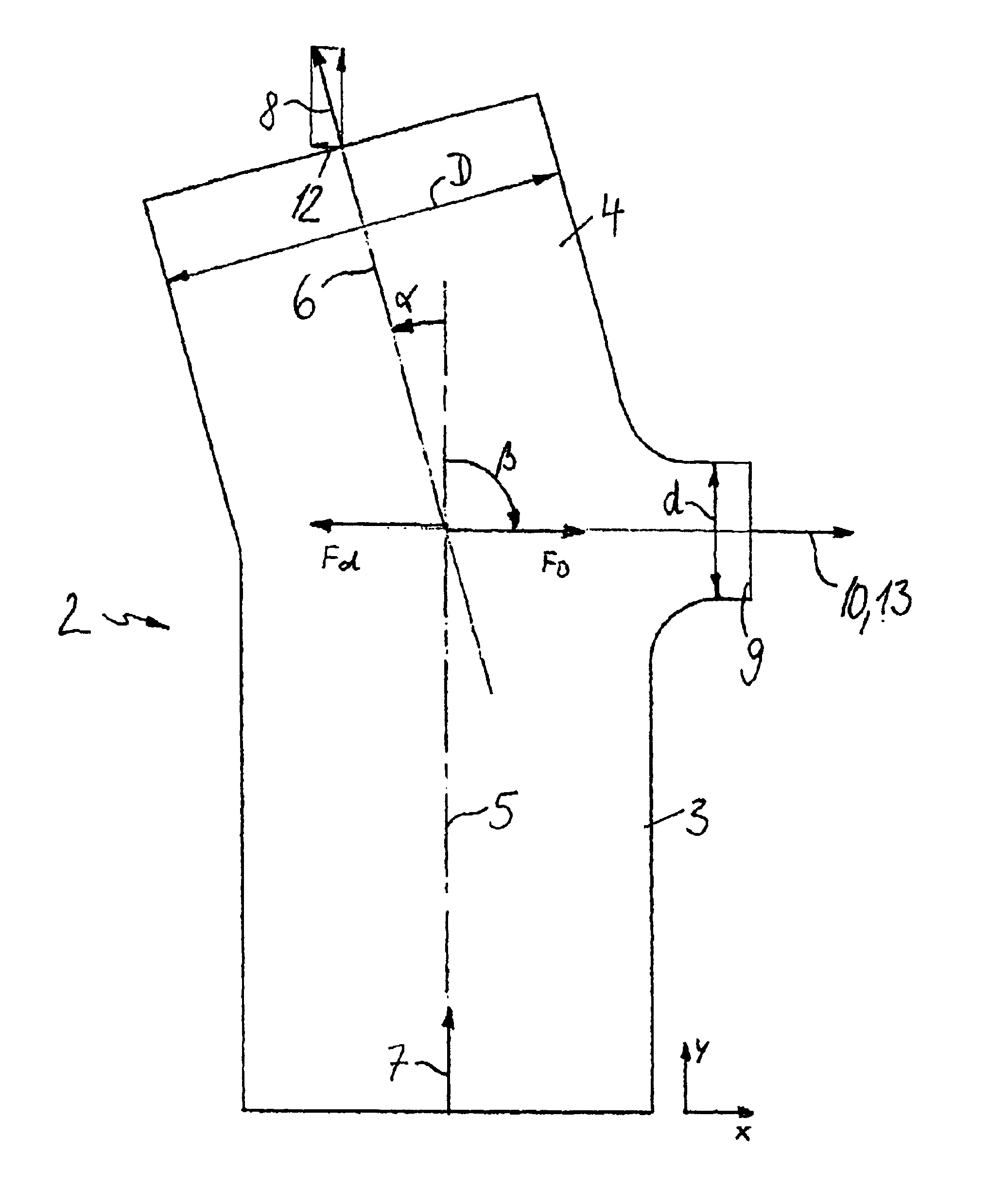
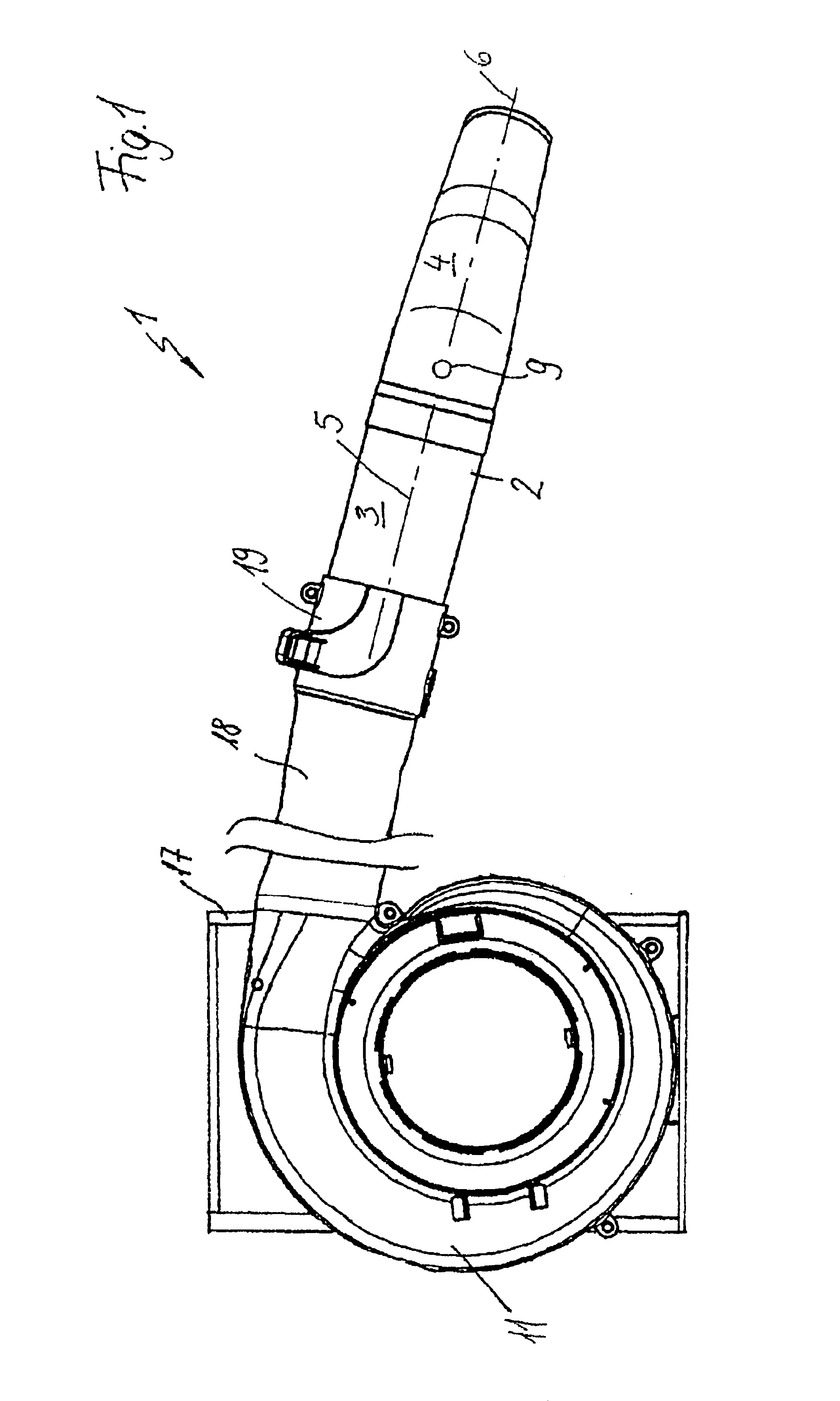
Referring now to the drawings in detail, FIG. 1 shows a blower 1 having a housing 11 to which a blower or discharge tube 2 can be secured via a discharge connector 19. The blower 1 is generally carried on the back via a pack 17, which is merely indicated in FIG. 1. The discharge tube 2 has a flexible portion 18 via which the air stream is guided about the body of an operator. Generally disposed on the discharge tube 2 is a handle, which is not illustrated in FIG. 1. An engine, especially an internal combustion engine, is generally disposed in the housing 11. The engine drives a fan that produces an air stream through the discharge tube 2. The discharge tube 2 is provided with a main portion 3 having a longitudinal axis 5, and a discharge portion 4 that extends at an angle to the main portion; the discharge portion 4 has a longitudinal axis 6. The angle between the longitudinal axes 5 and 6 of the main portion 3 and of the discharge portion 4 respectively is less than 180°. On that e...


PUM


Abstract

A blower having a discharge tube, which can be secured to a housing, for guiding a stream of air is provided. The air stream flows in a main stream direction in the discharge tube and in a discharge stream direction out of the discharge tube. The discharge stream direction forms an angle of greater than 0° with the main stream direction. The discharge stream direction has a transverse component that extends perpendicular to the main stream direction, which produces a force in the discharge tube perpendicular to the main stream direction. To reduce the transverse force produced in the discharge tube, a partial air stream is branched off out of the discharge tube and flows in a partial stream direction that has a compensation component that is directed opposite to the transverse component.

Description

BACKGROUND OF THE INVENTIONThe present invention relates to a blower having a discharge tube that can be secured to a housing and that serves for guiding a stream of air.A blower is known from U.S. Pat. No. 6,468,053. Blowers can have differently configured discharge tubes. To clean the edges of paths, discharge tubes expediently have a bent configuration. By changing the direction of the air stream in the discharge tube, a transverse force is produced that must be absorbed by the operator via the handle. In particular, with high-power blowers, great forces are required for this purpose, which can lead to rapid fatigue of the operator.It is therefore an object of the present invention to provide a blower of the aforementioned general type whereby during operation of such a blower low holding forces are required.BRIEF DESCRIPTION OF THE DRAWINGSThis object, and other objects and advantages of the present invention, will appear more clearly from the following specification in conjunct...

Claims


Application Information

Patent Timeline
Patent Type & Authority Patents(United States)
IPC IPC(8): E01H1/00E01H1/08F04D29/46
CPCF04D29/462E01H1/0809
Inventor SCHUTT, JORG
Owner ANDREAS STIHL AG & CO KG
Why Eureka
Try Eureka