
Bone suturing device

a bone suturing and bone technology, applied in the field of bone suturing devices, can solve the problems of bone trauma, high cost, and high complexity of the screwdriver used to perform the task, and achieve the effect of reducing the damage to the bon

Inactive Publication Date: 2005-01-18
BOSTON SCI SCIMED INC
View PDF50 Cites 65 Cited by
  • Summary
  • Abstract
  • Description
  • Claims
  • Application Information

AI Technical Summary

Benefits of technology

An object of some preferred embodiments of the invention is to provide a method of fixing a suture to a bone, while causing a minimum of damage to the bone and / or a minimum of implanted foreign objects, especially a minimum of implanted hard objects.
An aspect of some preferred embodiments of the invention relates to a drill bit for drilling in bone that includes an aperture for the extension of a needle through the aperture in the drill bit. Preferably, the aperture is in the side of the drill bit. In a preferred embodiment of the invention, the drill bit is mounted in a drill head that mechanically synchronizes the angular position of the drill bit and the extension of the needle. Alternatively, when the needles advance, the drill bits are released to rotate freely, so that the advance of a needle can rotate the drill bit to a desired angular position. Alternatively, an electrical synchronization method is used, for rotating the drill bits a complete number of rotations so that they are properly aligned when they stop. Alternatively, the needle exits through the tip of the drill bit. Optionally, the needle forms a hole in the drill bit when it extends. Alternatively or additionally, the drill bits reciprocate, instead of rotating.
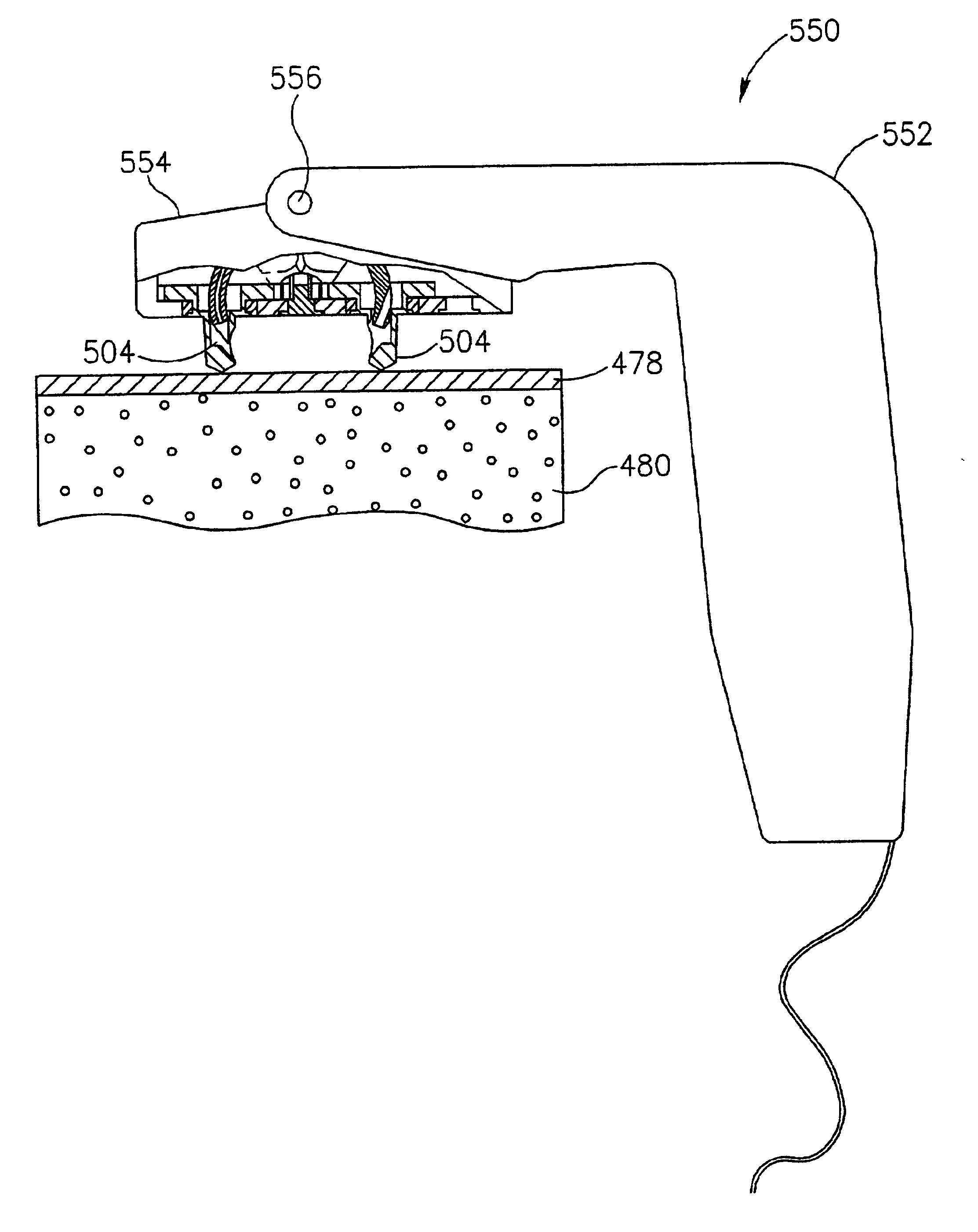
An aspect of some preferred embodiments of the invention relates to a method of transferring power from a power source to a tip of a bone-boring needle. Preferably, the power is applied using a lever. In a preferred embodiment of the invention, a main leverage point is provided at or about the needle. Optionally, a second leverage point is provided further away from the needle and remote from the power source. In a preferred embodiment of the invention, the power source is a human hand that moves a lever relative to a handle. The movement of this handle-lever is transferred, preferably using a cable or a bar to a second lever near the bone-boring needle. One desirable result of providing the leverage near the needle is that a less rugged construction is possible. Possibly, the bone-boring device is flexible rather than rigid.
An aspect of some preferred embodiments of the invention relates to a tip exchange mechanism, in which a sharp tip attached to a thread is exchanged between two needles that meet inside a bone. In a preferred embodiment of the invention, the tip is mounted at the end of a needle and forms a boring tip. When the two needles meet, the tip is captured by the other needle and retracts with it, pulling a thread along with it. Alternatively, the tip includes a long flexible extension, to which extension the thread is attached. Optionally, the extension is a super-elastic wire. Thus, the thread is not required to be inside the bone while the needles are in the bone and is less likely to be damaged. Also, such an extension is less likely to tear when the tip is pulled through the formed bore. Also, in some embodiments contact shearing forces may be applied to the thread. A flexible metallic extension is expected to resist such forces. Thus, a flexible extension may be provided, for example, also for a needle retraction mechanism as above, and not only for tip exchange mechanisms.
An aspect of some preferred embodiments of the invention relates to providing a bone-boring geometry that is not adversely affected by small errors in the placement of a bone-boring head against a bone. In a preferred embodiment of the invention, this is achieved by providing a needle which rotates on a hinge and providing a resting point of said bone boring head near a center of rotation of the needle. Alternatively or additionally, the invariance is achieved by providing a self-leveling bone-boring head that mechanically aligns itself relative to a bony area against which it is placed. Alternatively or additionally, the invariance is provided by an entire bone boring device being held by a hinged holder, so that the entire device rotates around the hinge to achieve an optimal placement against the bone.
An aspect of some preferred embodiments of the invention relates to a safety feature for preventing damage to or from circular needles that are inserted in a bone. In a preferred embodiment of the invention, when a device coupled to said needles is released, the releasing action first retracts the needles and only then allows the device to be moved.

Problems solved by technology

However, screwdrivers used to perform this task are often complex and / or expensive.
A disadvantage of both this and the previous techniques is that a hard foreign body is left implanted in the body.
Additionally, screws and bone anchors typically cause a considerable amount of trauma to the bone, which trauma is undesirable.
However, it is noted that drills usually damage a large amount of bone.

Method used


Image

  • Bone suturing device
  • Bone suturing device
  • Bone suturing device

Examples


Embodiment Construction

FIGS. 1A and 1B are schematic illustrations of a bone-boring device 100, in un-activated and activated configurations, respectively, in accordance with a preferred embodiment of the invention. Device 100 generally comprises a base 102 including a bone-boring head 104, a handle 106, possibly including a lever 108 and a shaft 110 interconnecting the handle and the base. In FIG. 1A, a pair of needles 112 of bone-boring head 104 are retracted. In FIG. 1B, when lever 108 is moved towards handle 106, needles 112 rotate and extend, boring a hole in adjacent bone.

The device shown in FIG. 1A and 1B is suitable for attaching sutures to an inside face of a pubic bone. Thus, needles 112 extend towards the handle. In use, boring-head 104 is placed against the pubic bone, upwards pressure being applied to handle 106 to assure good contact between the boring head and the bone, and then lever 108 is depressed to advance needles 112 and bore the hole. In devices for other uses, bone-boring head 104 ...


PUM


Abstract

A bone boring device and method, the device comprising a hinge, a handle coupled to the hinge, and at least one curved needle with a tip. The needle is rotatably mounted on the hinge such that when the tip is placed against bone and the needle is rotated on the hinge, the needle is urged and advanced into the bone. Preferably, the at least one needle is a first and a second needle. Alternatively, the needles may rotate about the same hinge or different hinges.

Description

FIELD OF THE INVENTIONThe present invention relates to forming channels through bones and especially to threading such channels with sutures.BACKGROUND OF THE INVENTIONAttaching a suture to a bone is a task that is well known in the art of surgery. A common solution is to screw a threaded screw into the bone. However, screwdrivers used to perform this task are often complex and / or expensive. Another solution described for example in U.S. Pat. No. 5,520,700 to Beyar et al., the disclosure of which is incorporated herein by reference, is to insert a threaded bone anchor into the bone. A disadvantage of both this and the previous techniques is that a hard foreign body is left implanted in the body. In general, it is desirable to leave as small an amount as possible of foreign material in the human bone. Additionally, screws and bone anchors typically cause a considerable amount of trauma to the bone, which trauma is undesirable.PCT publication WO 97 / 47246, the disclosure of which is in...

Claims


Application Information

Patent Timeline
IPC IPC(8): A61B17/16A61B17/17
CPCA61B17/0625A61B17/1604A61B17/1608A61B17/0482A61B17/0483A61B17/16Y10T408/96A61B17/1642A61B17/1796A61B2017/0472A61B2017/06052A61B2019/465A61B2090/065
Inventor HARARI, BOAZBEYAR, MORDECHAYGLOBERMAN, OREN
Owner BOSTON SCI SCIMED INC
Learn More