Satellite charge monitor

a satellite charge monitor and monitor technology, applied in the field of satellite charge monitors, can solve the problems of insufficient energy of electrons, inability to meet, temporary or permanent damage to satellite electronic circuits,

Inactive Publication Date: 2005-01-18
BALMAIN KEITH G +2
View PDF12 Cites 14 Cited by
  • Summary
  • Abstract
  • Description
  • Claims
  • Application Information

AI Technical Summary

Problems solved by technology

Unfortunately, the regions most heavily populated with high-energy charged particles are also the regions most frequently used by satellites, so that encounters between them are inevitable.
In general, the impacts of most types of energetic charged particles are capable of causing either temporary or permanent damage to satellite electronic circuits.
In particular, the electrons usually are not sufficiently energetic to pass through an entire satellite but they are energetic enough to become deeply embedded in the satellite dielectric materials that are used for both thermal and electrical insulation.
There, the electric charge can build up to the point of electrical breakdown and arc discharge, producing both electromagnetic interference and physical damage.
Wires or other conductors that are electrically “floating” (i.e. not grounded to the satellite frame) represent a special danger because they can store a large quantity of electrostatic energy which can be severely damaging when it discharges.

Method used


Image

  • Satellite charge monitor
  • Satellite charge monitor
  • Satellite charge monitor

Examples


Embodiment Construction

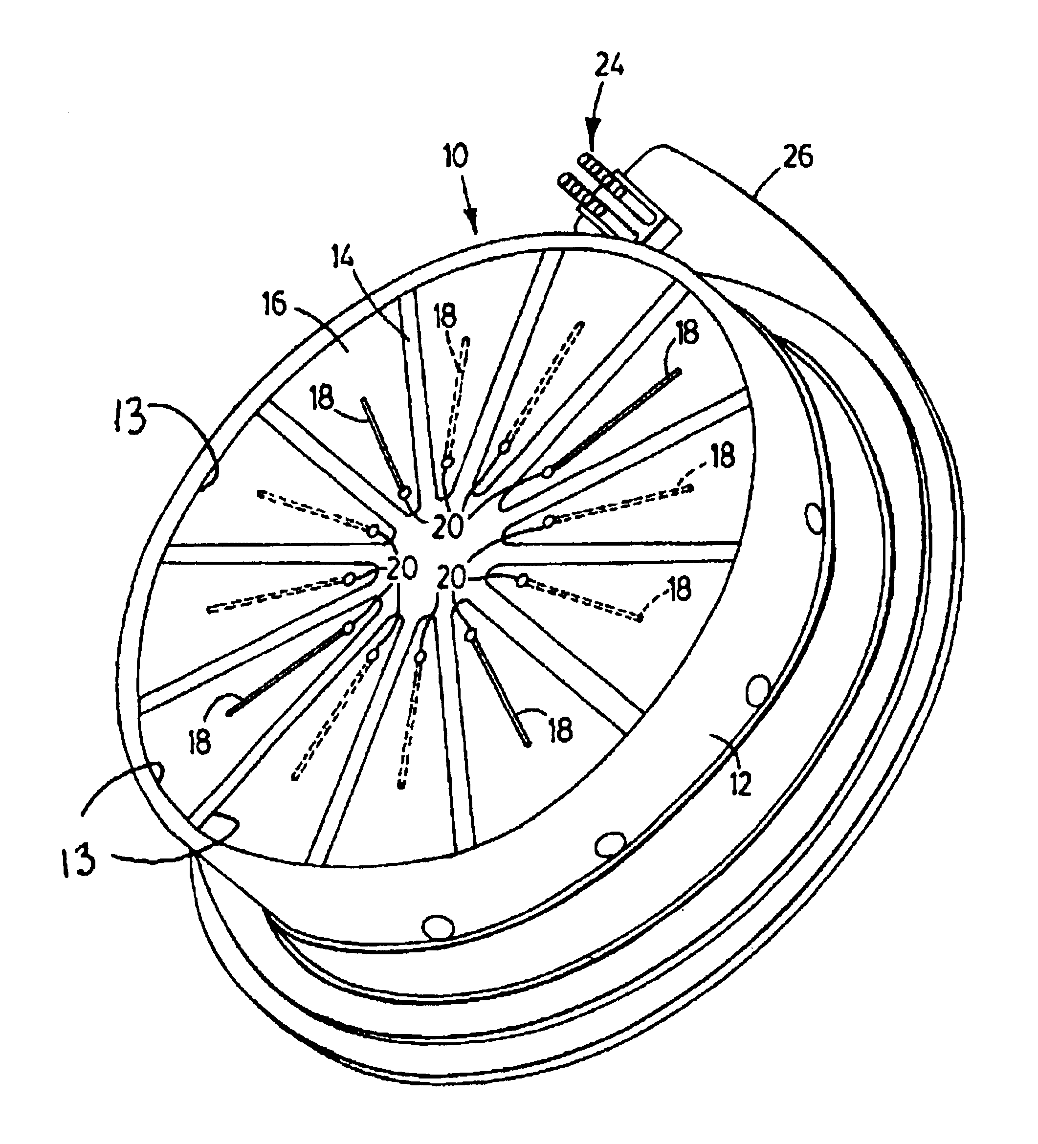
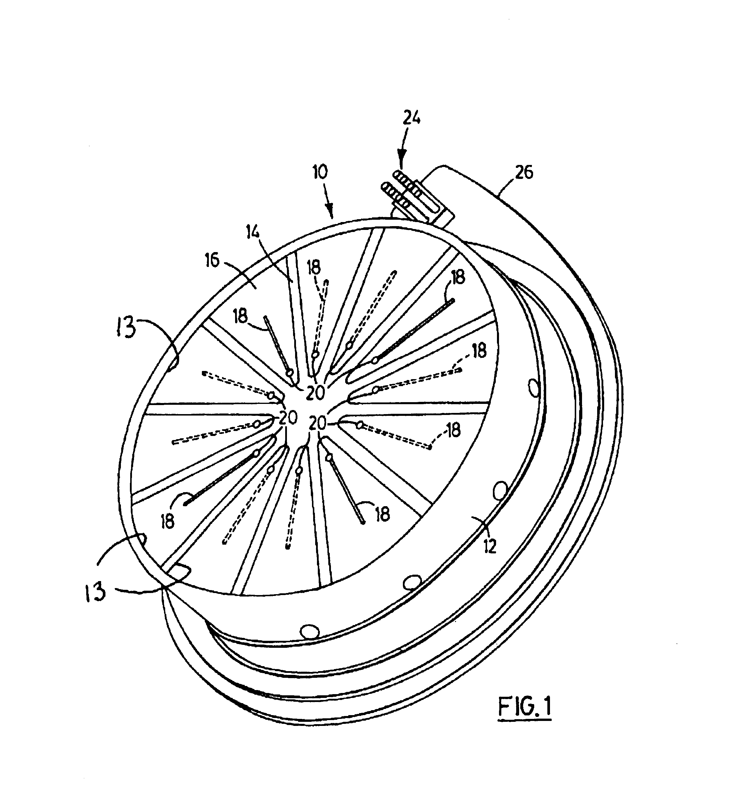
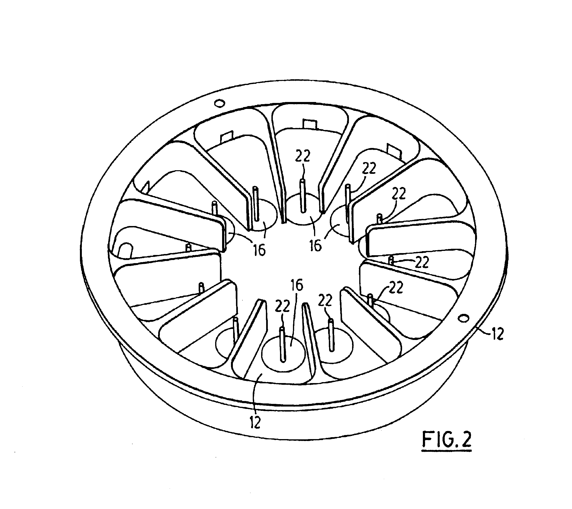
Referring to FIG. 1, a satellite charge monitor shown generally at 10 includes a metal or otherwise electrically conducting housing 12 made for example of lightweight aluminum or alloy of aluminum. Housing 12 is divided into twelve pie-shaped compartments 13 separated by electrically conducting partitions 14 (which form part of the electrically conducting housing 12) with a pie-shaped slab of dielectric material 16 located in each of the twelve compartments 13. Each dielectric slab 16 has an electrical conductor 18 (e.g. wires) embedded in it. These wires 18 are embedded at different depths in the dielectric slabs 16 so for example three of the wires 18 may be flush with the top surface exposed to space being located in a groove formed in the top surface of the dielectric slab 16. It will be understood that wires per se are not necessary but any electrically conducting material may be used such as conducting foils, ribbons to mention just a few. Another set of three wires may be emb...


PUM


Abstract

The present invention provides a charge monitor for satellites for monitoring build up of electric charge due to charge particle fluxes impinging on the satellite. In one aspect of the invention the charge monitor includes an electrically conducting housing including at least two compartments with each compartment including a dielectric slab contained therein. An electrically conducting electrode is embedded in each dielectric slab a pre-selected distance below a top surface of the dielectric slab, the housing being mountable on a satellite with the top surface of the dielectric slab facing outwardly into space away from the satellite whereby charged particles emitted from sources external to the satellite penetrate the dielectric slab resulting in charge accumulation in each electrically conducting electrode, each electrically conducting electrode being electrically isolated from all other electrically conducting electrodes in the electrically conducting housing. The monitor includes an electrical voltage detector for sensing the floating DC voltage developed on the electrically conducting electrode in each dielectric slab, due to the charge accumulation, and converting the DC voltage into an AC voltage representative of a charge buildup on each electrically conducting electrode.

Description

FIELD OF THE INVENTIONThis invention relates to a satellite charge monitor for monitoring electric charge buildup in various components making up a satellite.BACKGROUND OF THE INVENTIONEarth-orbiting satellites are now very numerous and provide a wide range of services, mostly in the areas of communications and remote sensing. These satellites find themselves immersed in a hostile environment of high-energy charged particles (electrons and ions) that originate in the Sun, are emitted as the “solar wind”, and eventually swirl around the Earth following complex paths that are strongly influenced by the Earth's magnetic field. Some of these charged particles enter the Earth's atmosphere to generate the visible aurora and others swoop past the Earth only to become involved in unstable oscillations that drive them backwards, once again towards the Earth. A fraction of all these particles eventually become trapped in relatively stable patterns known as the Van Allen belts (sometimes calle...

Claims


Application Information

Patent Timeline
Patent Type & Authority Patents(United States)
IPC IPC(8): B64G1/54B64G1/22
CPCB64G1/546B64G1/54G01R29/24
Inventor BALMAIN, KEITH G.KREMER, PETER C.DUBOIS, GERALD R.
Owner BALMAIN KEITH G
Why Eureka
Try Eureka