Current mirror based multi-channel leakage current monitor circuit and method

a current monitor and current mirror technology, applied in the field of electronic devices, can solve the problems of affecting the yield of usable dies obtained, the performance of dynamic circuits (e.g., wide-operating range (or) gates) starts to degrade with increasing the keeper size, and the register file and cache are particularly susceptible to this type of performance degradation

Inactive Publication Date: 2005-01-18
INTEL CORP
View PDF3 Cites 27 Cited by
  • Summary
  • Abstract
  • Description
  • Claims
  • Application Information

AI Technical Summary

Problems solved by technology

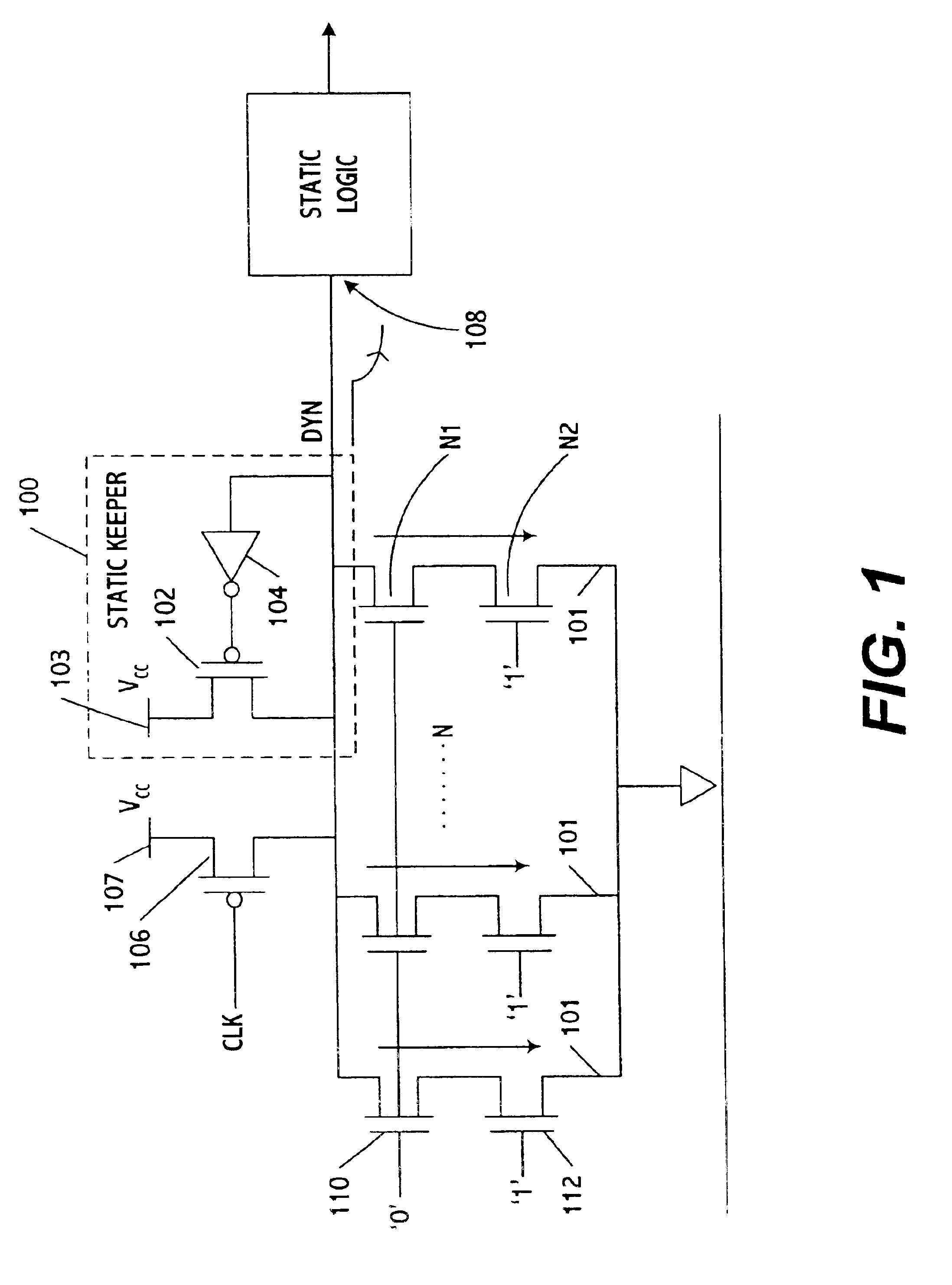
However, the performance of dynamic circuits (e.g, wide-operating range (OR) gates) starts degrading with increasing keeper size.
Register files and caches are particularly susceptible to this type of performance degradation, since wide-OR type dynamic circuits are often used in these types of circuits.
Thi

Method used


Image

  • Current mirror based multi-channel leakage current monitor circuit and method
  • Current mirror based multi-channel leakage current monitor circuit and method
  • Current mirror based multi-channel leakage current monitor circuit and method

Examples


Embodiment Construction

In the following detailed description of the various exemplary embodiments, reference is made to the accompanying drawings that show, by way of illustration, specific embodiments in which the invention made be practiced. In the drawings, like numerals describe substantially similar components throughout the several views. These exemplary embodiments are described in sufficient detail to enable those skilled in the art to practice the invention and changes may be made without departing from the spirit and scope of the exemplary embodiments of the present invention. Moreover, it is to be understood that various embodiments of the invention, although different, are not necessarily mutually exclusive. For example, a particular feature, structure, or characteristic described in one embodiment may be included within other embodiments. Therefore, the following detailed description is not to be taken in a limiting sense. The scope of the present invention is delineated by the claims, along ...


PUM


Abstract

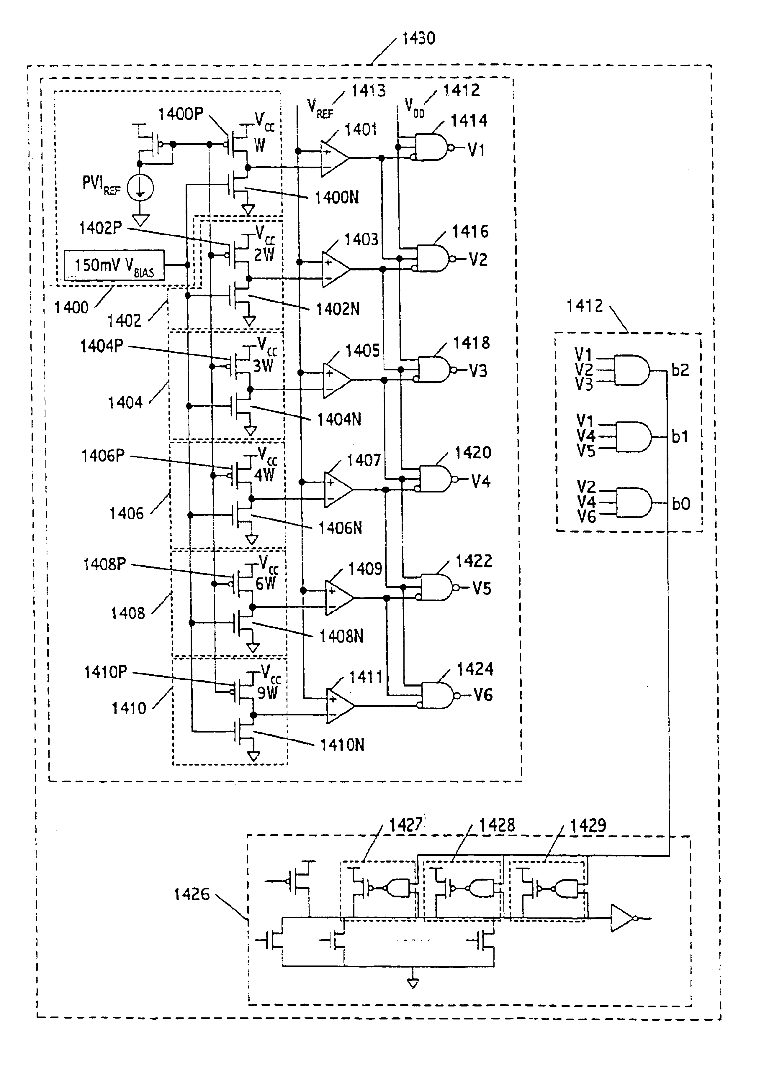
A current mirror multi-channel leakage monitor circuit and method measures die leakage and generates digital keeper control bits to control a process compensated dynamic circuit. The leakage monitor enables high resolution on-chip leakage measurements in multiple locations on a die, thereby saving test time and enabling both die to die and within die process compensation.

Description

BACKGROUND OF THE INVENTION1. Field of the InventionThe field of invention generally relates to electronics and more particularly to a variable keeper strength process compensated dynamic circuit and method and a leakage current monitor circuit and method.2. Background of the Related ArtThe increasing leakage (e.g. current leakage in a transistor) in scaled technologies has forced designers to increase keeper sizes in dynamic circuits to obtain acceptable levels of robustness. However, the performance of dynamic circuits (e.g, wide-operating range (OR) gates) starts degrading with increasing keeper size. Register files and caches are particularly susceptible to this type of performance degradation, since wide-OR type dynamic circuits are often used in these types of circuits. Along with the increase in leakage, die-to-die (D2D) and within-die (WID) process variations cause the leakage distribution to become wider and wider. This process variation adversely affects the yield of usabl...

Claims


Application Information

Patent Timeline
IPC IPC(8): G01R31/28G01R31/30G11C29/50G11C29/04
CPCG01R31/3012G11C29/50G11C2029/5006G11C2029/5004
Inventor HSU, STEVEN K.KRISHNAMURTHY, RAMKIM, CHRIS HYUNG-IL
Owner INTEL CORP
Why Eureka
Try Eureka