Planar antenna having linear and circular polarization

a planar antenna and linear polarization technology, applied in the field of antennas, can solve the problems of limiting the use of the antenna, the only use of the planar antenna is linear and circular polarization, and the cumbersomeness of the dish antenna

Inactive Publication Date: 2005-01-18
SAMSUNG THALES
View PDF20 Cites 21 Cited by
  • Summary
  • Abstract
  • Description
  • Claims
  • Application Information

AI Technical Summary

Benefits of technology

To solve the above-described problems, it is an object of the present invention to provide an antenna having linear and circular polarization, which uses dipoles as radiation elements, and has an orthogonal characteristic in both linear and circular polarization, the antenna being embodied by using two plates and the front and back sides of the plates effectively.
The present invention discloses a planar antenna that accommodates either linear or circular polarization having an orthogonal characteristic during transmission and reception in a wideband. By using two folds of printed-circuit-board type plates, the antenna of the present invention can minimize insertion loss, weight, and thickness. However, since isolated radiation elements are insufficient, the frequency band has a limitation.

Problems solved by technology

Dish antennas are sometimes cumbersome due to their bulkiness.
However, most planar antennas can only utilize one of linear and circular polarization, not both.
This characteristic limits the use of the planar antenna such that the antenna cannot be used for both transmission and reception.
I have found that there are disadvantages to current dish antennas and current planar antennas.
While these recent efforts provide advantages, I note that they fail to adequately provide an improved planar anntenna having linear and circular polarization.

Method used


Image

  • Planar antenna having linear and circular polarization
  • Planar antenna having linear and circular polarization
  • Planar antenna having linear and circular polarization

Examples


Embodiment Construction

While the present invention will be described more fully hereinafter with reference to the accompanying drawings, in which preferred embodiments of the present invention are shown, it is to be understood at the outset of the description which follows that persons of skill in the appropriate arts may modify the invention here described while still achieving the favorable results of this invention. Accordingly, the description which follows is to be understood as being a broad, teaching disclosure directed to persons of skill in the appropriate arts, and not as limiting upon the present invention.

Illustrative embodiments of the invention are described below. In the interest of clarity, not all features of an actual implementation are described. In the following description, well-known functions, constructions, and configurations are not described in detail since they could obscure the invention with unnecessary detail. It will be appreciated that in the development of any actual embod...


PUM


Abstract

An antenna is located at the end of a wireless communication system, or other radio system, and more particularly, a wideband planar antenna with linear and circular polarization uses different polarization for transmission or reception to increase the isolation between the transmission and reception by suggestion and using a type of radiation element. The disclosed antenna is more efficient than other similar antennas that can transmit / receive linear or circular polarization. The disclosed invention makes it possible to pr vide an antenna having dual polarization, which has an orthogonal characteristic in both linear and circular polarization, and which can lower the height of the antenna by embodying a micro strip planar antenna which has linear and circular polarization that has high gain over a wide frequency band, and which transmits / receives linear or circular polarization.

Description

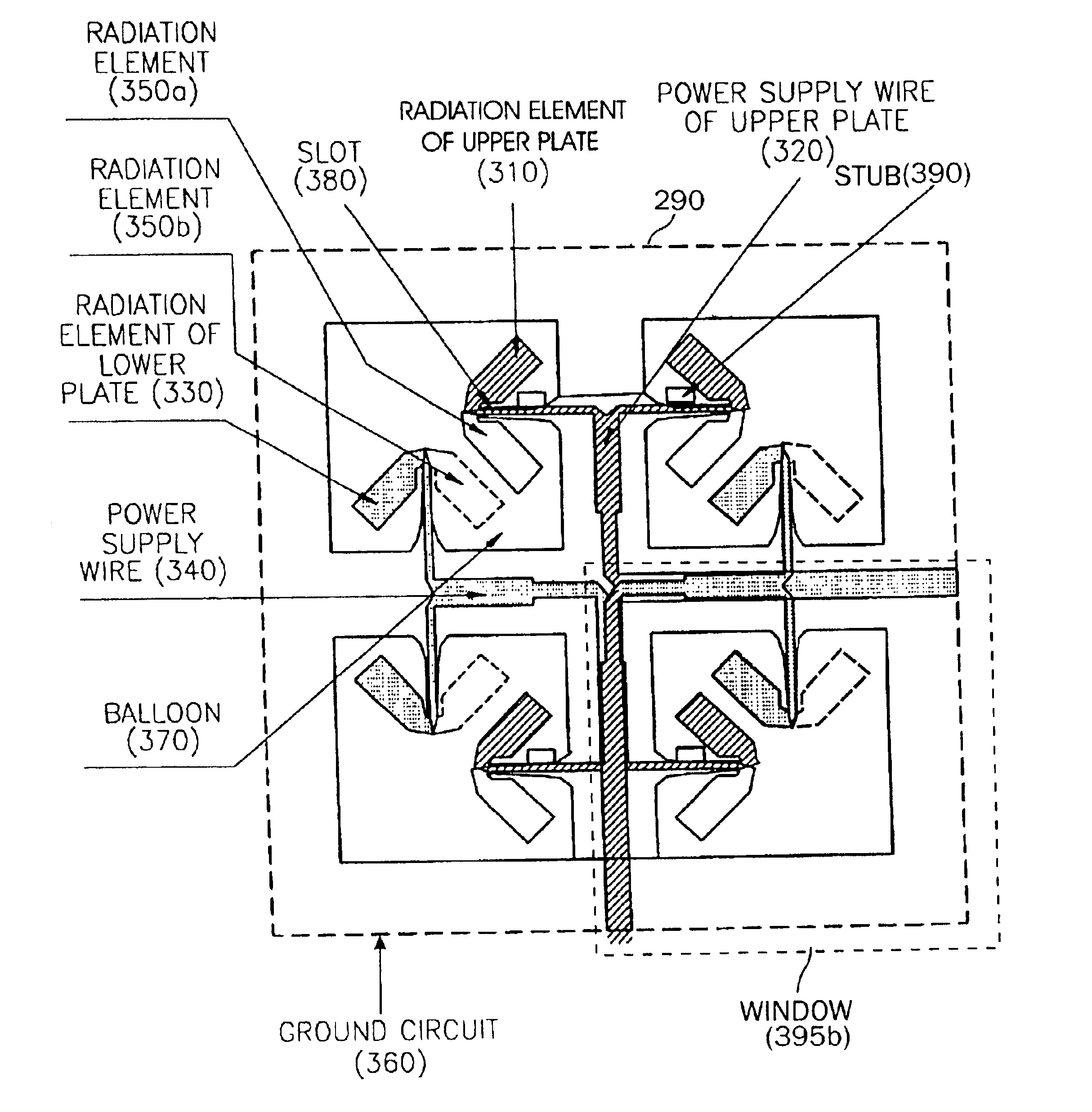
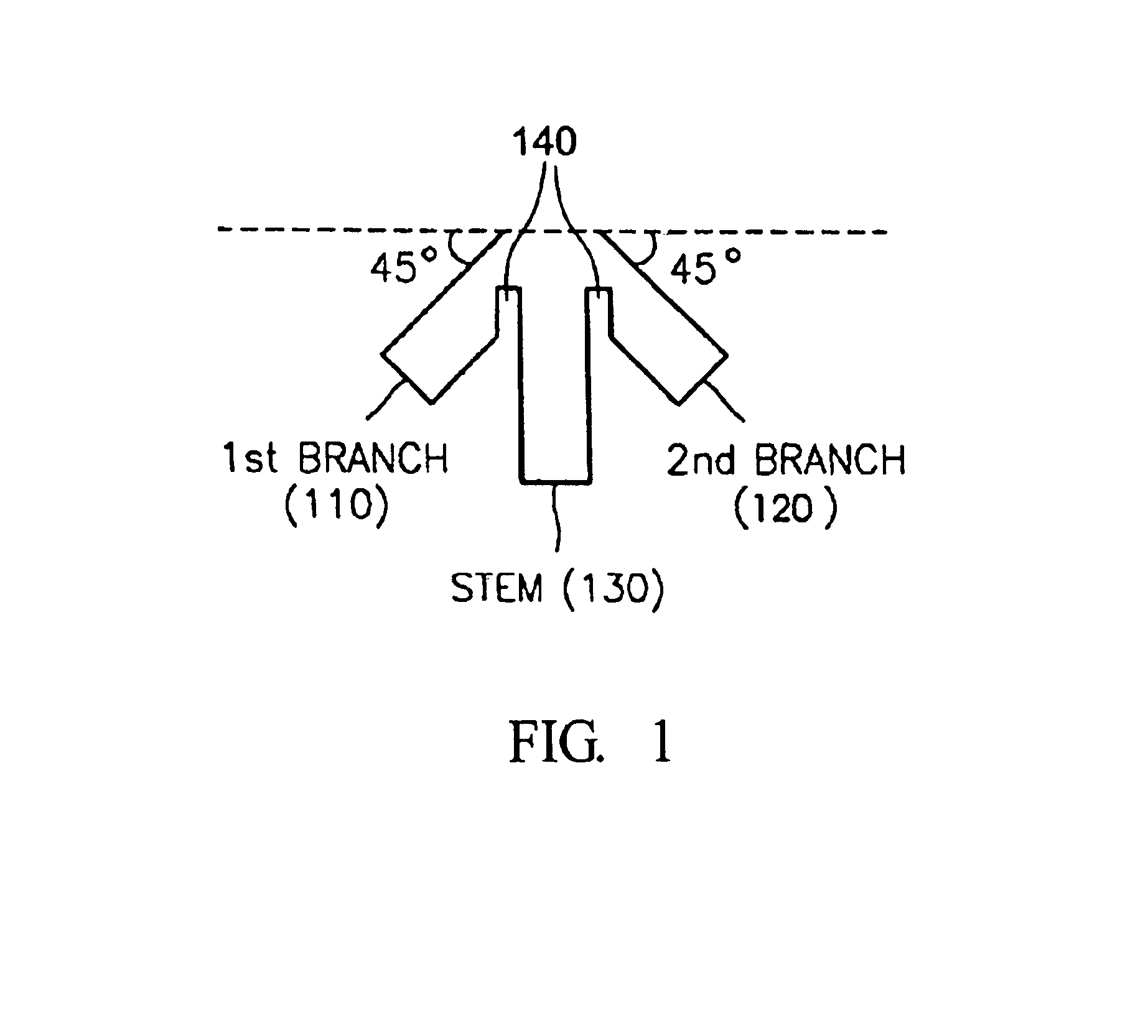
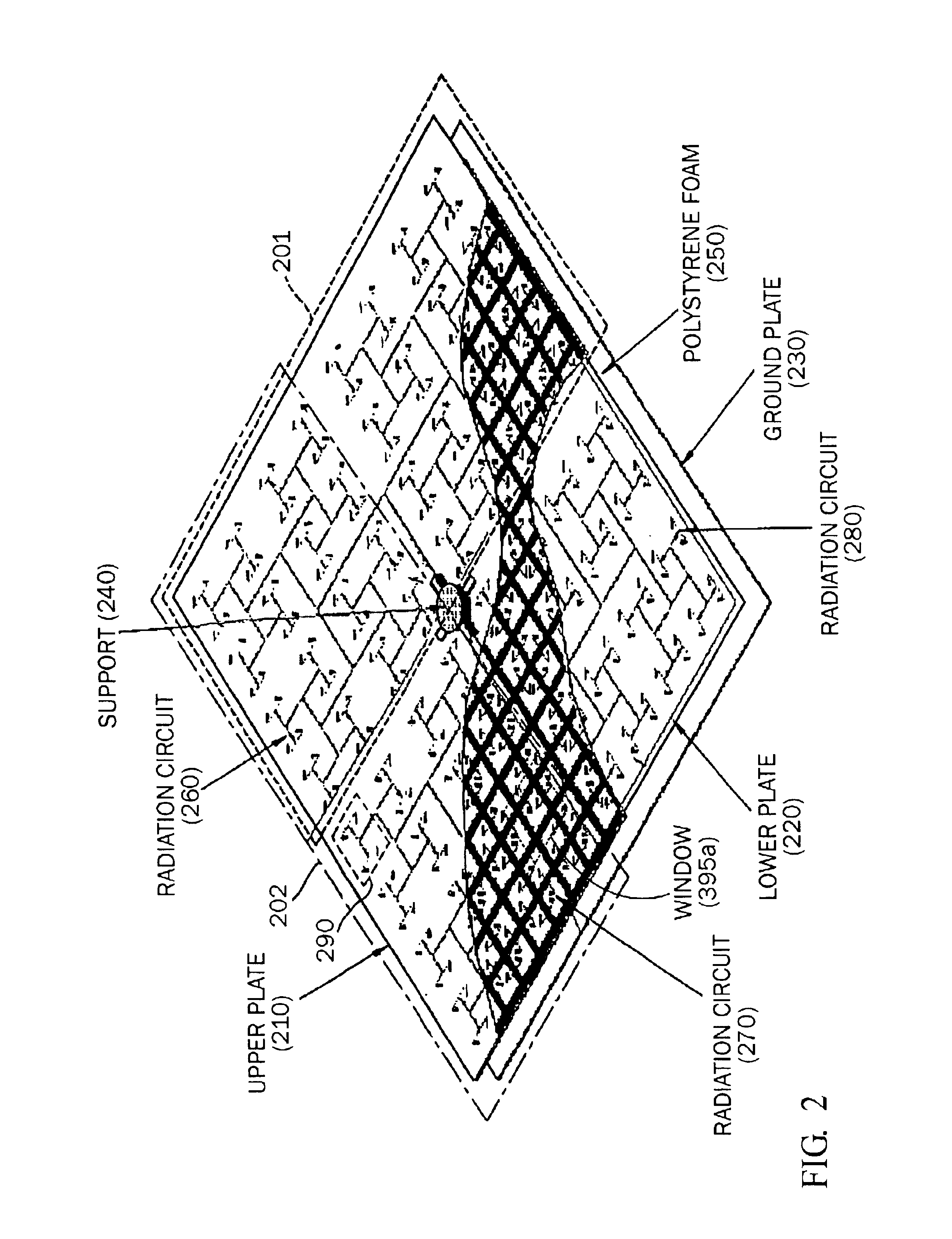
CLAIM OF PRIORITYThis application claims priority to an application entitled “PLANNER ANTENNA HAVING LINEAR AND CIRCULAR POLARIZATION”, filed in the Korean Industrial Property Office on May 27, 2002 and assigned Serial No. 2002-29322, the contents of which are hereby incorporated by reference.BACKGROUND OF THE INVENTION1. Technical FieldThe present invention relates to an antenna that is located at the end of a wireless communication system, or other radio system, and more particularly, to a wideband planar antenna having linear and circular polarization, which uses different polarization for transmission and reception to increase the isolation between transmission and reception by suggesting and using a type of a radiation element.2. Related ArtA dish antenna is commonly used for a satellite communication service because the dish antenna has a simple structure and it can easily form dual circular polarization. Dish antennas are sometimes cumbersome due to their bulkiness. For this ...

Claims


Application Information

Patent Timeline
Patent Type & Authority Patents(United States)
IPC IPC(8): H01Q21/24H01Q1/38H01Q9/04H01Q21/26H01Q1/52H01Q9/06H01Q9/28H01Q1/00H01Q21/00H01Q21/06H01Q13/08
CPCH01Q1/38H01Q1/525H01Q9/065H01Q21/26H01Q21/0075H01Q21/062H01Q21/24H01Q9/285H01Q13/08
Inventor YOON, WON-SANGYEVTYUSHKIN, GENNADI
Owner SAMSUNG THALES
Why Eureka
Try Eureka