Wide angle paraconic reflector antenna

a wide angle, paraconic technology, applied in the direction of non-resonant long antennas, antennas, electrically long antennas, etc., can solve the problems of compromising pattern coverage, limiting the size and weight of spaceborne antenna platforms, and raising attendant concerns, so as to achieve high gain and reduce size and weight

Inactive Publication Date: 2005-01-18
LOCKHEED MARTIN CORP
View PDF10 Cites 35 Cited by
  • Summary
  • Abstract
  • Description
  • Claims
  • Application Information

AI Technical Summary

Benefits of technology

In view of the foregoing, an object of the present invention to provide an antenna that provides high gain and wide-angle coverage with reduced size and weight, and that is particularly apt for spaceborne applications.
It is also an object of the present invention to provide an antenna that yields wide-angle coverage with reduced feed componentry interference, and that is particularly apt for spaceborne applications.
The reflector and feed may be provided so that a focal point or ring of the reflector is centered upon a feed phase center or feed ring of the feed antenna. For example, a curved reflecting surface may be utilized that has a focal point located at the center of the feed phase center or feed ring. Alternatively, a curved reflecting surface may be utilized that has a focal ring centered upon the feed phase center or feed ring. In either case, the feed antenna preferably may be circularly symmetric with the reflector and centered upon a longitudinal center axis of the main reflector to facilitate beam uniformity. In other arrangements, the feed phase center or feed ring may be offset from the antenna focal point or ring by a predetermined amount to obtain a specific far-field beam pattern.
To increase efficiency and / or optimize aperture illumination, the reflector antenna may further include a lens positioned over the feed antenna and supportably interconnected to the post. For example, a hemispherical, dielectric lens may be employed. The lens may include an aperture for receiving the post therethrough.
For this embodiment, the paraconic reflector shape may be defined so that the curved reflecting surface has an apex, wherein the reflector presents a continuous reflecting surface across the lateral extent thereof. The apex may be disposed on the longitudinal center axis and optically aligned with the center of the feed antenna to facilitate beam uniformity.
In conjunction with this embodiment, the feed antenna may be fed via feed cabling or fiber optic lines that extend from a backside of the feed housing and wind about the radiolucent support. In this regard, feed cabling may be provided within an absorber (e.g. a carbon-based foam or honeycomb) that reduces radiation scatter. The feed cabling may be wound around the support at a predetermined angle to spread any beam blockage over an azimuth area. For example, the predetermined angle should preferably be selected so that the feed cabling is wound no more than once around the support.

Problems solved by technology

In the later regard, while an increased diameter of a paraboloidal reflector can increase its gain and efficiency, the desire to limit the size and weight of spaceborne antenna platforms presents a challenging trade-off.
Further, the placement of feed componentry can compromise pattern coverage, particularly where wide-angle coverage is desired.
Additionally, feed componentry placement in spaceborne applications raises attendant concerns in relation to environmental exposure and outboard mass.

Method used


Image

  • Wide angle paraconic reflector antenna
  • Wide angle paraconic reflector antenna
  • Wide angle paraconic reflector antenna

Examples


Embodiment Construction

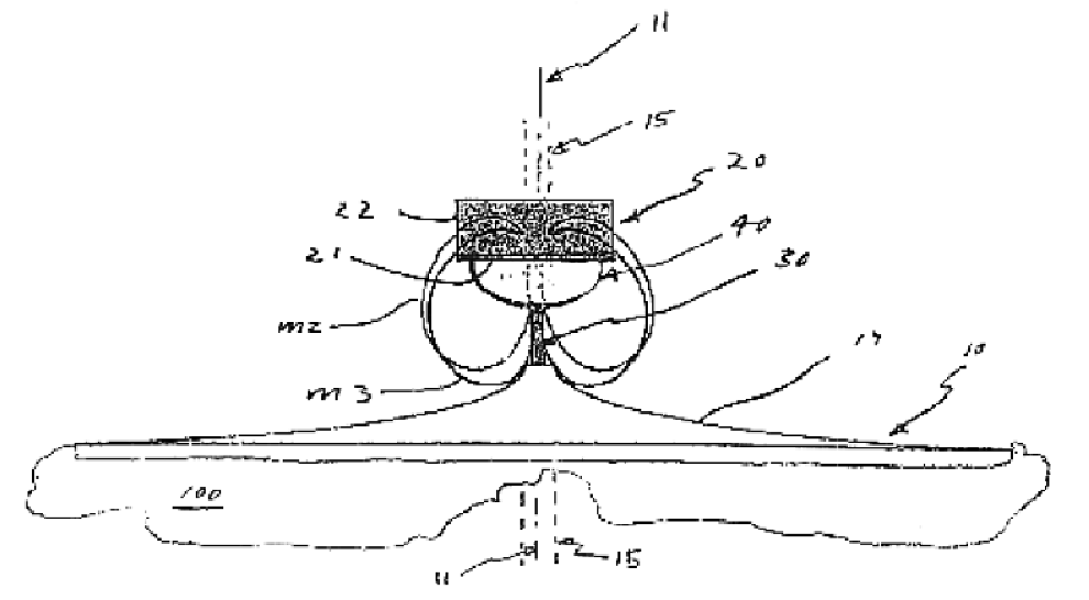
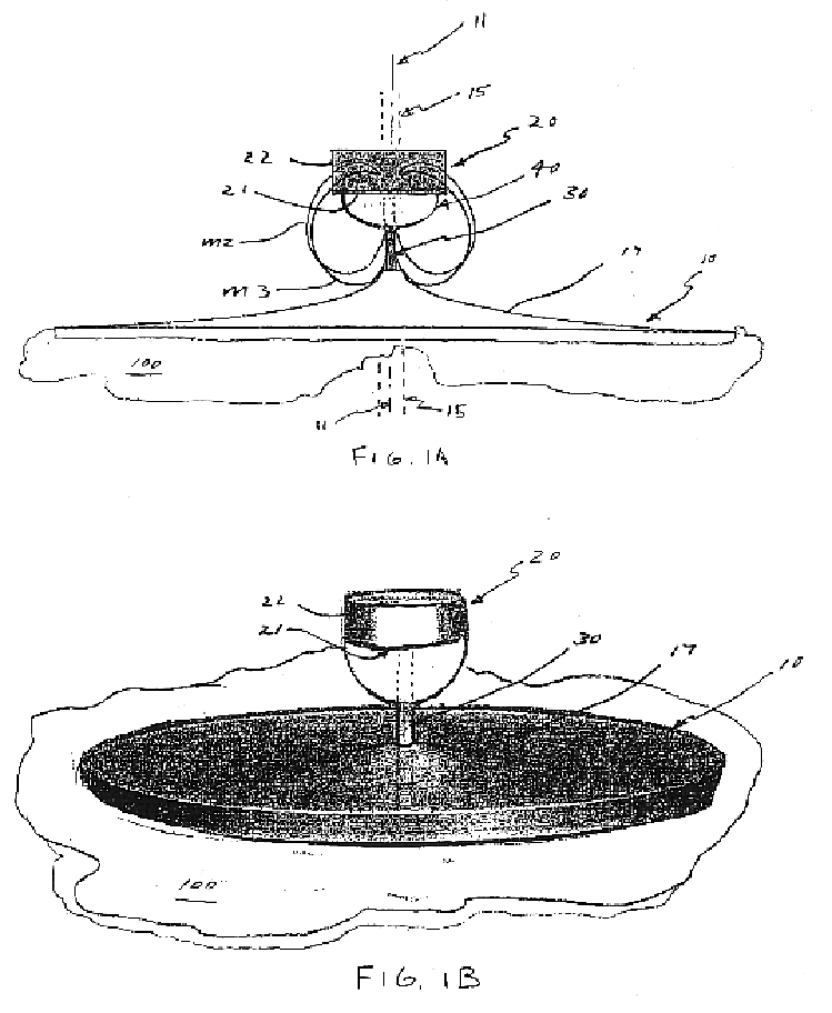
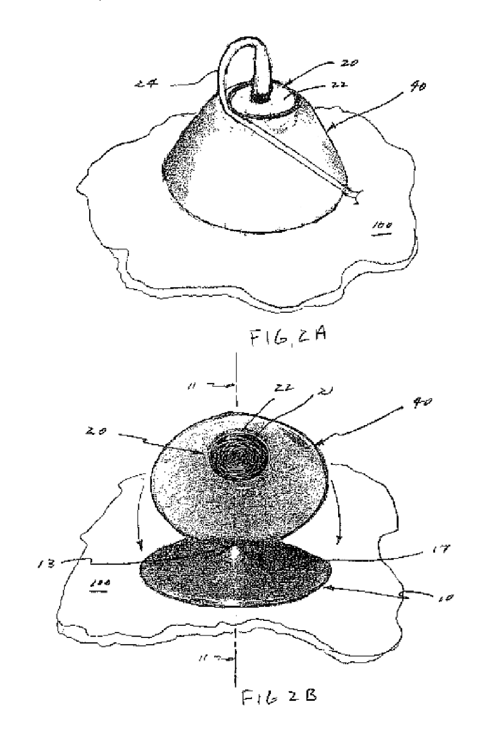
In the embodiment of FIGS. 1A and 1B a paraconic reflector antenna comprises a reflector 10 and a feed 20 supportably disposed in opposing relation to the reflector 10 by post 30. The reflector 10 and post 30 may be mounted on a support structure 100, such as the deck of a spaceborne vehicle (e.g. a satellite). In operation, radiation beams are transmitted by feed 20 and reflected by reflector 10 to yield wide-angle, annular coverage.

The post 30 may be located on the longitudinal center axis 11. In this regard, the post 30 may be positioned in a center hole provided through reflector 10.

The reflector 10 includes a curved reflecting surface 17 that is defined by a curve symmetrically rotated about a longitudinal center axis 11. As shown by FIG. 1, the curved reflecting surface 17 may generally define a truncated cone having dish-shaped sides in a side view. The curve used to define the curved reflecting surface 17 may be selected to have a focal point on or laterally displaced from t...


PUM


Abstract

A wide-angle reflector antenna that substantially eliminates pattern blockage is provided. The reflector antenna includes a paraconic reflector and a feed supportably located in opposed relation to the reflector surface. A curved reflecting surface of the reflector is formed by symmetrically rotating a curve around a longitudinal center axis, wherein the curve also defines an apex on the longitudinal center axis. The curve's focal point may be located on the longitudinal center axis or laterally displaced therefrom.

Description

FIELD OF THE INVENTIONThe present invention relates to reflector-type antennas, and more particularly, to a reflector antenna that provides wide-angle coverage, e.g. an annular or conical pattern. The inventive reflector antenna is particularly apt for spaceborne applications.BACKGROUND OF THE INVENTIONAntennas are configured to transmit and receive radiation beams having particular, desired patterns. Generally, antennas are reciprocal in that they exhibit similar properties in both transmission and reception modes of operation. As such, while descriptions of antenna performance are often expressed in terms of either transmission or reception, the capability to operate comparably in either mode is understood. In this regard, the terms “aperture illumination,”“beam” and “radiation pattern” may pertain to either a transmission or reception mode of operation. Relatedly, the same antenna “feed” may be employed for both the transmission and reception of signals.As noted, different antenn...

Claims


Application Information

Patent Timeline
Patent Type & Authority Patents(United States)
IPC IPC(8): H01Q13/00H01Q11/10H01Q19/10H01Q11/00
CPCH01Q11/10H01Q19/102H01Q13/00
Inventor CENCICH, TOMMILLIGAN, TOMBURFORD, JASON
Owner LOCKHEED MARTIN CORP
Why Eureka
Try Eureka