Vapor cycle system (VCS) with thermal reservoirs for reducing requisite VCS power and size with intermittent heat loads

a vapor cycle and thermal reservoir technology, applied in refrigeration machines, refrigeration components, lighting and heating apparatuses, etc., can solve the problems of difficult precision cooling, large space and weight consumption of conventional systems, and high power consumption

Inactive Publication Date: 2005-01-18
HONEYWELL INT INC
View PDF13 Cites 20 Cited by
  • Summary
  • Abstract
  • Description
  • Claims
  • Application Information

AI Technical Summary

Problems solved by technology

A conventional system would require significant space and weight consumption while also being extremely power intensive.
Precision cooling, however, is difficult, as the spent coolant is returned to the reservoir and mixed with the supply coolant.

Method used


Image

  • Vapor cycle system (VCS) with thermal reservoirs for reducing requisite VCS power and size with intermittent heat loads
  • Vapor cycle system (VCS) with thermal reservoirs for reducing requisite VCS power and size with intermittent heat loads

Examples


example

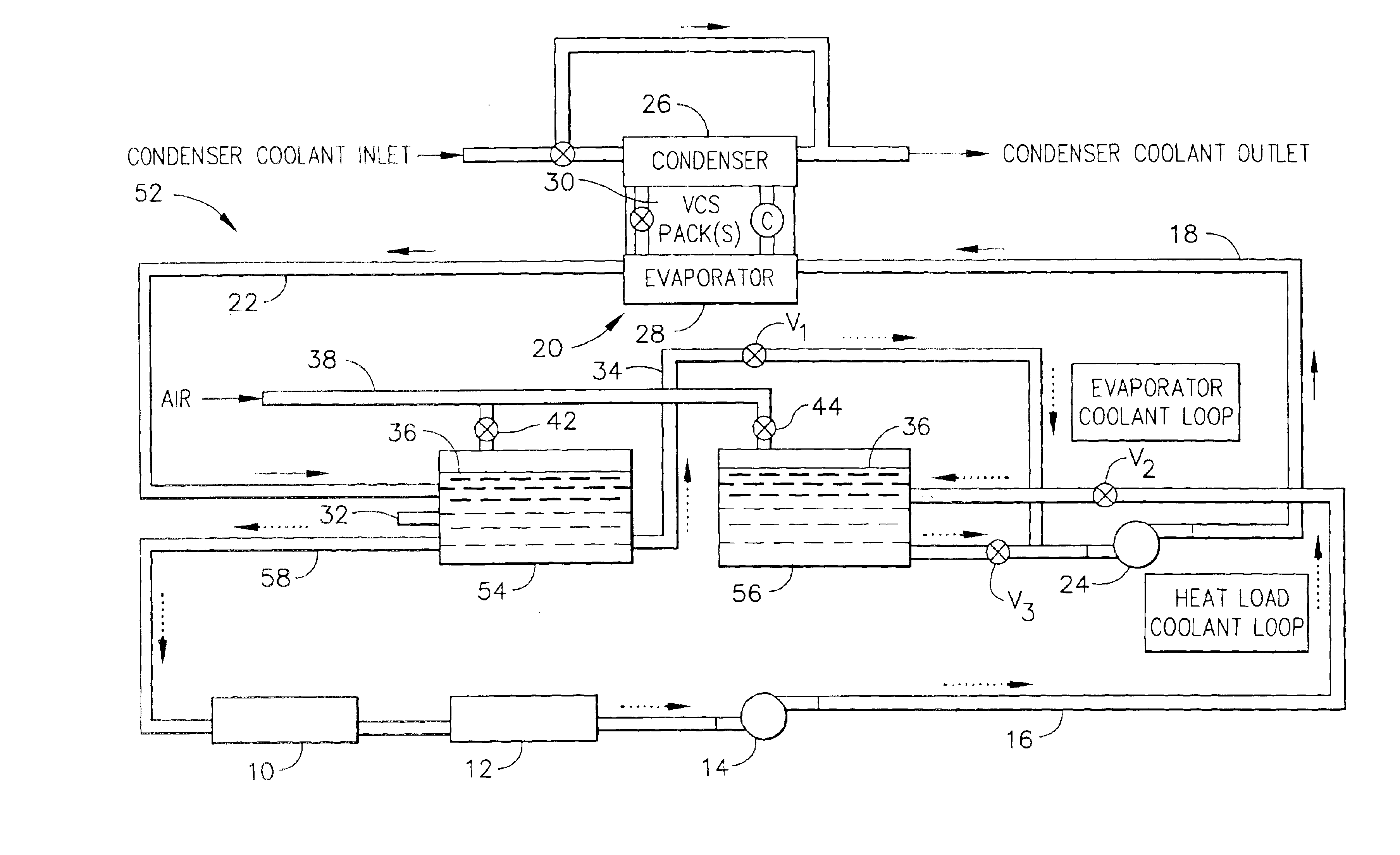
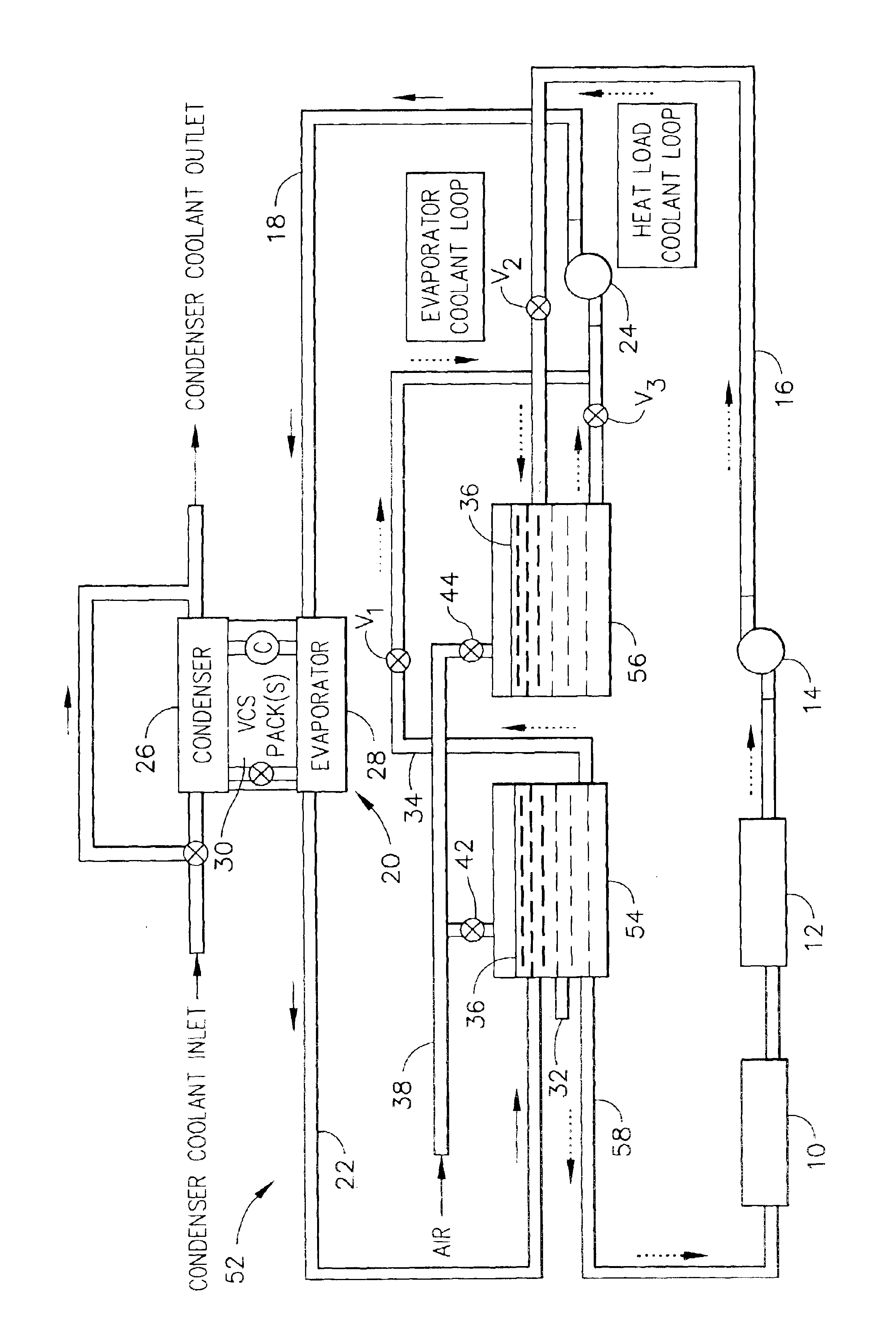
Referring still to the FIGURE, one embodiment of the present invention, uses VCS system 52 to provide precise thermal control to a first laser heat load 10 and a second laser heat load 12. First laser heat load 10 requires a coolant controlled input temperature of approximately 40° F. The coolant output from first laser heat load 10 is fed to second laser heat load 12.

Initially, the cold water reservoir 54 is filled with about 170 lbs of ambient temperature water. While less water may be used in this example, excess water is preferred so that there is no chance of the system running dry. In this “cool down” operating condition, valve V1 is opened and pump 24 feeds the ambient temperature water through cooldown loop output line 34, hot water reservoir output line 18, and cooling system 20. The output coolant, having the precisely controlled inlet temperature, returns to cold water reservoir 54 via cold water reservoir input line 22. Preferably, water flows through the system during t...


PUM


Abstract

A system for providing coolant to a heat load includes a first coolant reservoir providing coolant to the heat load and a second coolant reservoir receiving used coolant after passing through the heat load. The used coolant is refreshed by a cooling apparatus which receives the used coolant from the second coolant reservoir, cools the used coolant, and supplies refreshed coolant to said first coolant reservoir. The resulting dual reservoir system offers significant reductions in the size, weight and power of the vapor cycle system (VCS) equipment while providing for accurate temperature control of the coolant delivered to the heat load.

Description

BACKGROUND OF THE INVENTIONThe present invention relates generally to a coolant providing system having thermal reservoirs for reducing the requisite system power and size, and, more specifically, to a vapor cycle system (VCS) which provides apparatus and methods for providing a coolant to a heat load. The present invention is especially beneficial for applications having intermittent heat loads which require a high degree of accurate temperature control.Solid state lasers are known to use various cooling devices to prevent a thermal overload. In many applications, solid state lasers require a precisely controlled inlet coolant temperature. A high power solid state laser could potentially require in excess of 100 tons instantaneous cooling during laser firing. A conventional system would require significant space and weight consumption while also being extremely power intensive.U.S. Pat. No. 5,608,748 discloses a cooling liquid flowing from a reservoir, through the laser cavity, and...

Claims


Application Information

Patent Timeline
Patent Type & Authority Patents(United States)
IPC IPC(8): F25B25/00
CPCF25B25/005F25B2400/24
Inventor GIBSON, RICHARD A.
Owner HONEYWELL INT INC
Why Eureka
Try Eureka