
Technique for effectively processing and dynamically routing communication calls

a communication call and dynamic routing technology, applied in the field of communication system and method, can solve the problems of caller experience a long wait time, operator cannot answer all calls, center may be deluged, etc., and achieve the effect of maintaining the quality of servi

Inactive Publication Date: 2005-01-18
GRAPE TECH GROUP
View PDF30 Cites 98 Cited by
  • Summary
  • Abstract
  • Description
  • Claims
  • Application Information

AI Technical Summary

Benefits of technology

[0008]In an alternative embodiment, before a call from a communication network is routed to any call center, a processor in the network queries the remote call routing server for an appropriate call center to which the call is routed, thereby avoiding an overflow condition in the receiving call center and rerouting the call.

Problems solved by technology

A call center sometimes may be deluged with telephone calls such that the operators cannot answer all calls immediately after the calls come in.
As a result, a caller may experience a long wait time and feel frustrated.
However, this technique may actually cause a delay in answering those calls which can otherwise be answered immediately by the receiving call center.
However, a major shortcoming of this technique is its inflexibility to route overflow calls in a call center to any available call center not next thereto in the sequence.

Method used


Image

  • Technique for effectively processing and dynamically routing communication calls
  • Technique for effectively processing and dynamically routing communication calls
  • Technique for effectively processing and dynamically routing communication calls

Examples


second embodiment

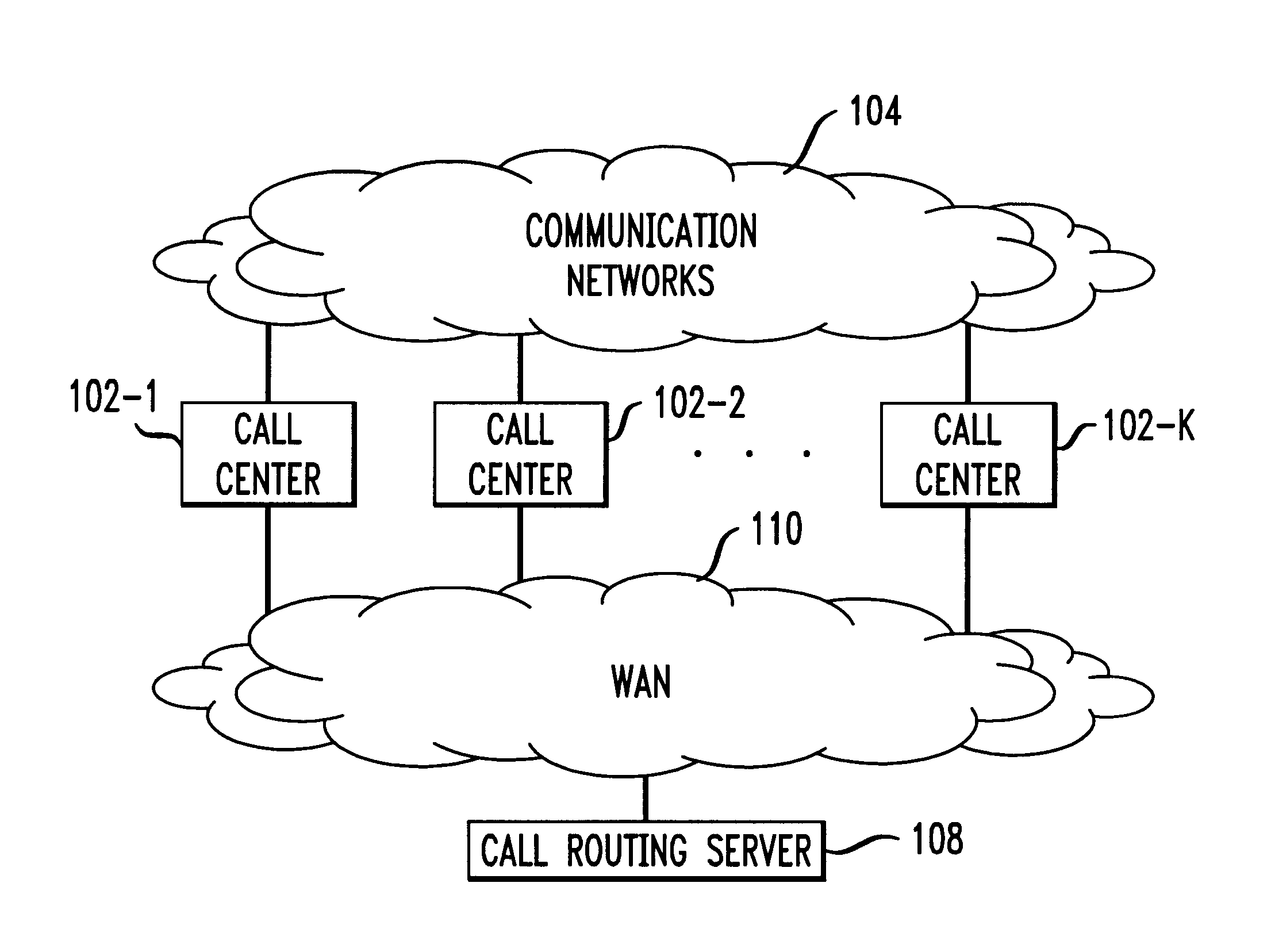
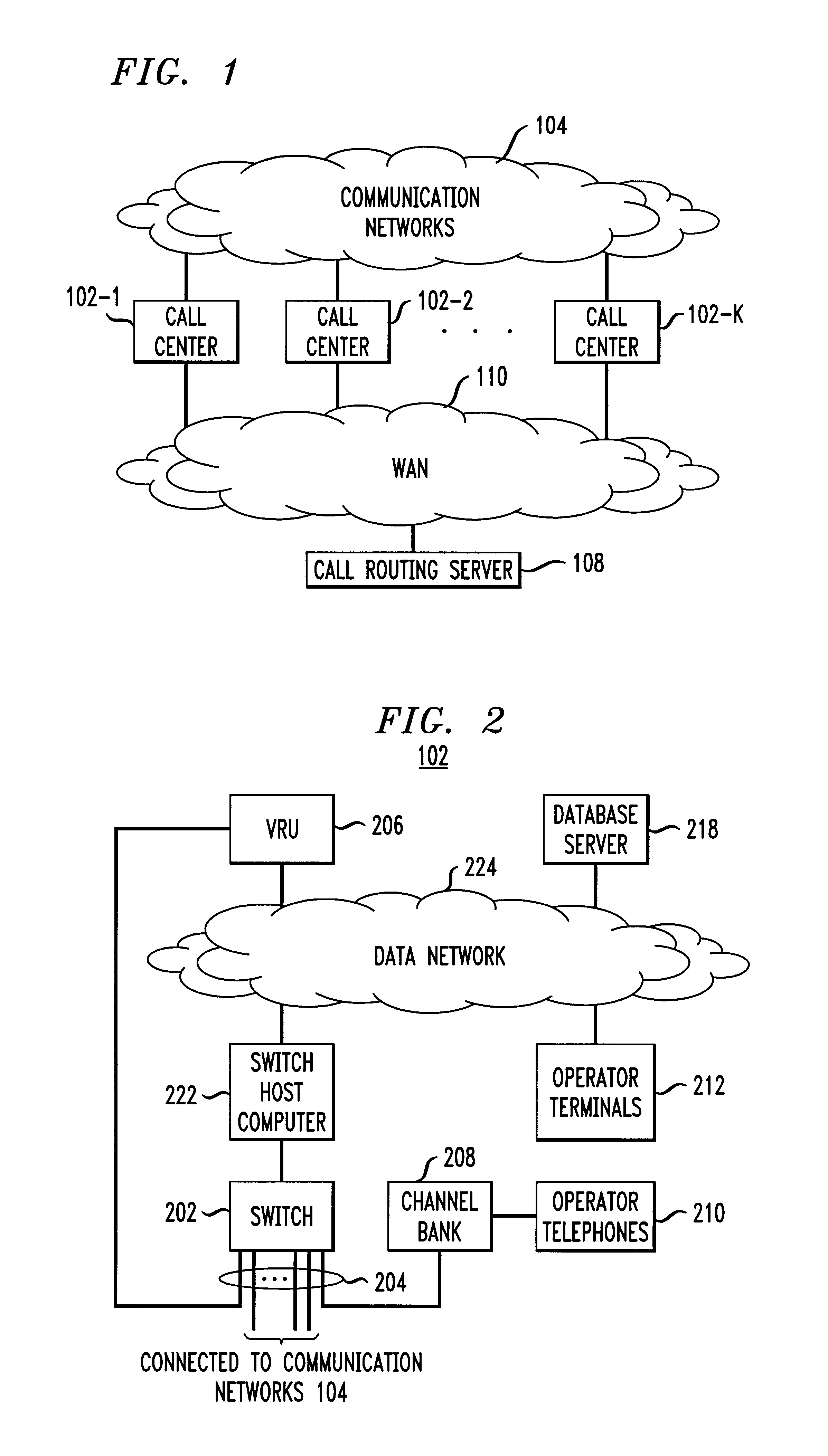
[0056]FIG. 8 illustrates an arrangement for use in the invention. In this embodiment, the routing of calls to call centers 102-1 through 102-K is orchestrated by network processor 907 in communication networks 104, with the help of call routing server 108. Specifically, when one such call to a call center at a predetermined telephone number is routed through switching facility 910, having learned the predetermined telephone number, facility 910 queries network processor 907 for an available call center to which the call is to be routed. In response, network processor 907 in turn queries call routing server 108 for such an available call center, e.g., via WAN 110. Server 108 then identifies any available call center to accommodate the call, in accordance with a routine similar to that of FIG. 8 although, here, server 108 is in communication with network processor 907, as opposed to a call controller in a call center. Once processor 907 receives from server 108 the routing information...

third embodiment

[0057]FIG. 9 illustrates another arrangement for use in the invention. In this arrangement a call to a call center, say, center 1005, at a predetermined telephone number is normally routed by switching facility 1003 in first communication network 1002 to the call center, without regard for its availability in the first instance as in the arrangement of FIG. 1. However, in accordance with an aspect of the invention, disaster recovery measures are put in place here in case center 1005 is out of commission and the calls directed to center 1005 which would otherwise go unanswered are rerouted to alternate call centers. To that end, as soon as center 1005 is identified to be out of order, switching facility 1003 is programmed to switch each call otherwise directed to call center 1005 to switching facility 1009 in second communication network 1006. Facility 1009 is connected to network processor 1011 similar to above-described network processor 907. Like processor 907, processor 1011 quer...


PUM


Abstract

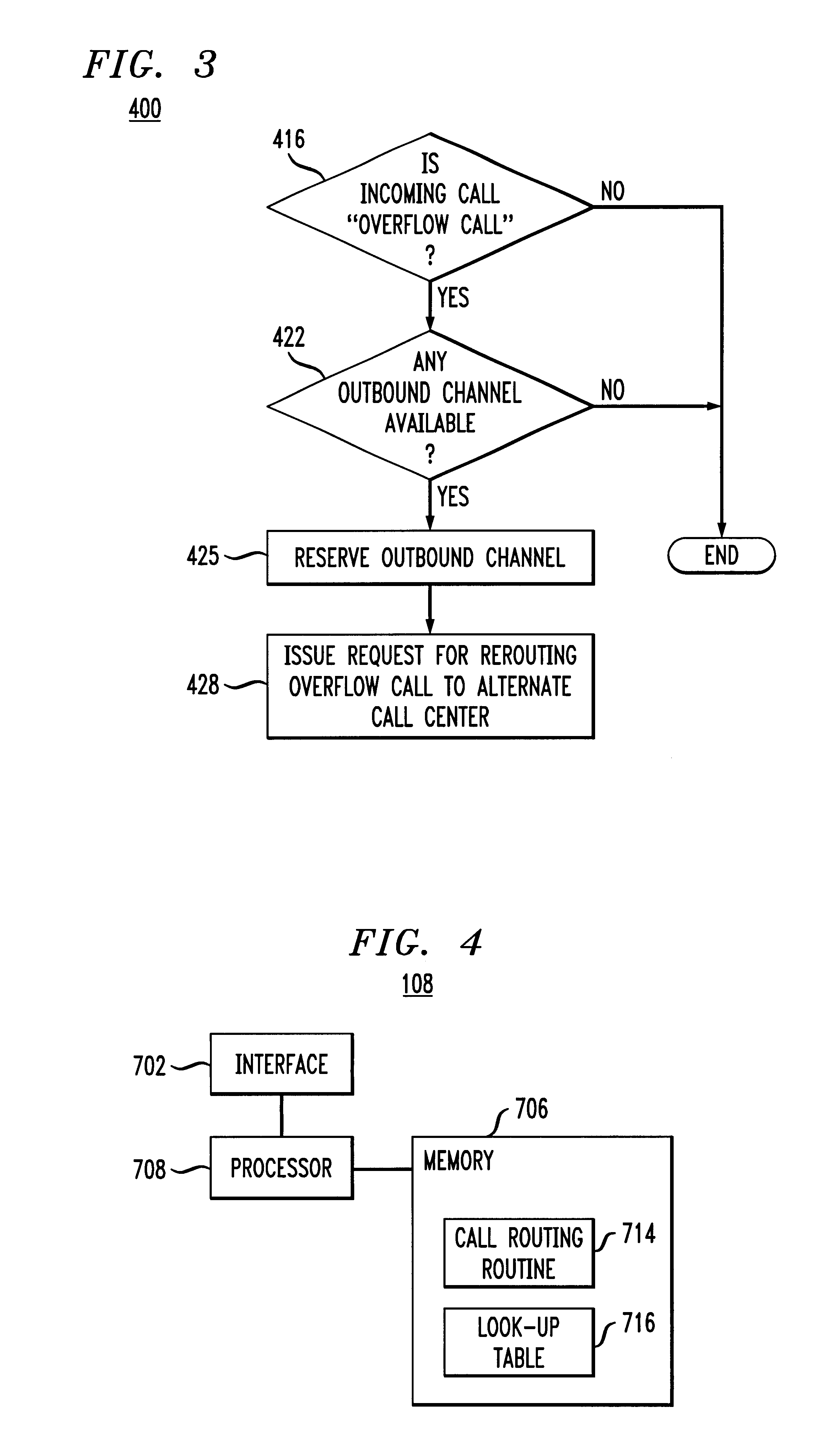
In an arrangement where calls are directed to different call centers, each call center based on selected metric measures determines whether an incoming call is an “overflow” call to be rerouted to an alternate call center. These metric measures may include, e.g., the number of operators in the call center answering calls, the number of calls in queue to be answered, etc. Once an overflow call is identified, the call center reserves an outbound communication channel in anticipation of rerouting the call, and transmits a call rerouting request to a call routing server. In accordance with the invention, the server identifies an appropriate alternate call center for receiving the overflow call, and communicates routing information including an identity of the alternate call center to the overflow call center. The latter based on the received routing information transfers the call to the appropriate alternate call center.

Description

FIELD OF THE INVENTION[0002]The invention relates generally to a communications system and method, and in particular to a system and method for processing and controlling a flow of communication calls.BACKGROUND OF THE INVENTION[0003]It is commonplace that large companies and information service providers set up call centers in different geographic areas to handle telephone inquiries from customers. After receiving one such customer call, a call center normally assigns the call to an appropriate service representative, operator and / or interactive voice response (IVR) unit therein to attend to the call. For example, a customer of an information service provider may call a designated number for information, and the call is then routed to a call center where an operator can provide the customer with the desired phone numbers and addresses of particular persons and establishments, directions, movie listings, restaurant recommendations, etc.[0004]A call center sometimes may be deluged wi...

Claims


Application Information

Patent Timeline
Patent Type & Authority Patents(United States)
IPC IPC(8): H04M3/36H04M3/523H04M3/50
CPCH04M3/5237H04M3/36
Inventor ELSEY, NICHOLAS J.
Owner GRAPE TECH GROUP
Learn More