Broadband wireless shared resource network architecture

a shared resource network and wireless technology, applied in data switching networks, digital transmission, substation equipment, etc., can solve the problems of adverse effects of free-space optical communications, achieve improved network performance, improve network efficiency, and reduce unit costs

Inactive Publication Date: 2005-01-18
SPRINT CORPORATION
View PDF7 Cites 20 Cited by
  • Summary
  • Abstract
  • Description
  • Claims
  • Application Information

AI Technical Summary

Benefits of technology

The invention helps solve the above problems with a broadband wireless network architecture that allows service providers to share resources. Advantageously, physical, spectral, or logical separation is maintained, so service providers can avoid conflicts and maintain their own quality-of-service. Advantageously, the ability to share resources allows multiple service providers to leverage their combined traffic volumes to improve economies of scale and lower unit costs. The lower costs may be passed on to the customers of the service providers or used to improve network performance.

Problems solved by technology

Free-space optical communications are adversely affected by fog and snow, so in areas with heavy fog or snow patterns, the high-GHz wireless signal might be the primary receive signal, and the free-space optical signal might be the secondary receive signal.

Method used


Image

  • Broadband wireless shared resource network architecture
  • Broadband wireless shared resource network architecture
  • Broadband wireless shared resource network architecture

Examples


Embodiment Construction

Prior Art Broadband Wireless Network Architecture—FIG. 1

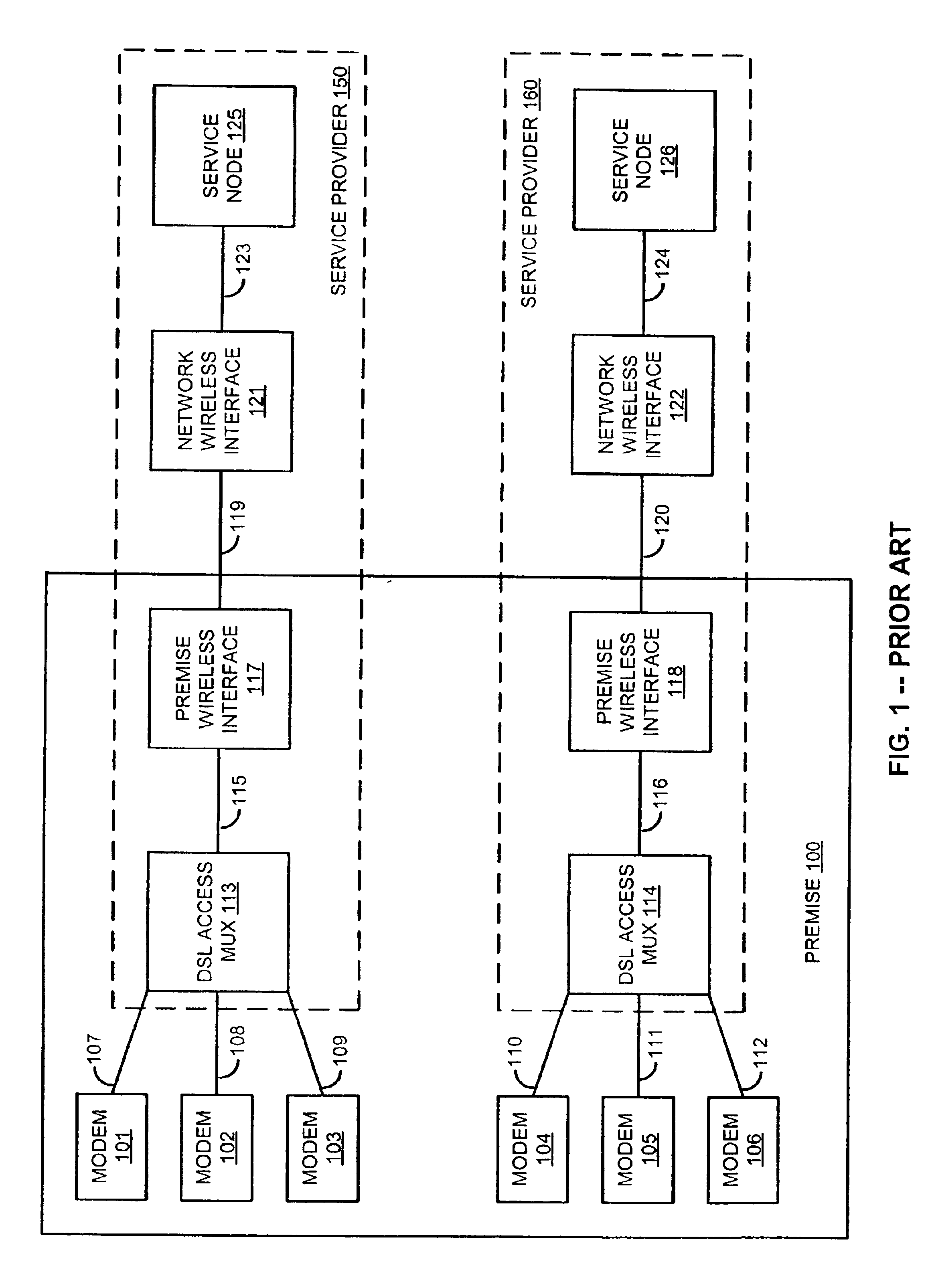
Prior to a description of the invention, a description of the prior art is first provided to facilitate a better appreciation and understanding of the invention as described further below. FIG. 1 illustrates a broadband wireless network architecture in the prior art. FIG. 1 shows premise 100, service provider 150, and service provider 160. Premise 100 includes DSL modems 101-106, DSL connections 107-112, DSL access multiplexers 113-114, premise connections 115-116, and premise wireless interfaces 117-118. Service provider 150 includes DSL access multiplexer 113, premise connection 115, premise wireless interface 117, wireless communication link 119, network wireless interface 121, network connection 123, and service node 125. Service provider 160 includes DSL access multiplexer 114, premise connection 116, premise wireless interface 118, wireless communication link 120, network wireless interface 122, network connection 124, an...


PUM


Abstract

A DSL access multiplexer exchanges communications between DSL connections and premise connections. A premise wireless interface exchanges the communications between the premise connections and a wireless communication link. A network wireless interface exchanges the communications between the wireless communication link and network connections. The DSL connections, premise connections, and network connections are physically allocated to different service providers. The DSL access multiplexer, premise wireless interface, and network wireless interface maintain physical, spectral, and/or logical separation between the customer communications of the different service providers.

Description

BACKGROUND OF THE INVENTION1. Field of the InventionThe invention is related to the field of broadband wireless communications, and in particular, to a network architecture that allows for shared resources among service providers.2. Statement of the ProblemBroadband wireless technologies are being deployed by service providers to provide communication services to their customers. The network architectures being used in this deployment maintain a physical separation between the equipment of the different service providers. This physical separation avoids conflicts between service providers and allows each service provider to maintain their own quality-of-service. Different service providers operating in the same area also use different wireless spectrum for the same reason.This physical separation also prevents resource sharing among service providers. Unfortunately, the inability to share resources inhibits multiple service providers from leveraging their combined traffic volumes to...

Claims


Application Information

Patent Timeline
Patent Type & Authority Patents(United States)
IPC IPC(8): H04B1/38H04L12/28H04M11/06
CPCH04M11/062H04L12/5692
Inventor JOHNSON, HAROLD W.
Owner SPRINT CORPORATION
Why Eureka
Try Eureka