
Absorption refrigerator

a refrigerator and refrigerator cabinet technology, applied in the field of absorption refrigerators, can solve the problems of limiting the maximum cooling capacity, and affecting so as to improve the efficiency of use, reduce the pull-down time, and enhance the heat transfer

Inactive Publication Date: 2005-01-25
DOMETIC APPLIANCES
View PDF10 Cites 155 Cited by
  • Summary
  • Abstract
  • Description
  • Claims
  • Application Information

AI Technical Summary

Benefits of technology

This configuration enhances the refrigeration system's efficiency by minimizing heat transfer through the outer walls, maintaining desired freezer temperatures, and reducing the time required to reach the desired temperature at startup, while also improving cooling performance in both compartments.

Problems solved by technology

A problem with this type of absorption refrigerator cabinets is a considerable heat transfer through the rear wall from the outside of the cabinet to the inside.
Heat transfer into the refrigerator cabinet is particularly disadvantageous at absorption refrigerators used in mobile applications.
At absorption refrigerators, the physical dimensions of the refrigeration system limit the maximum cooling capacity.
This makes it difficult to keep the respective compartments at the desired temperature.
This problem is particularly severe for the freezer compartment, for which, at modern mobile refrigerators, it is desired to keep the temperature as low as −18° C. Any heat which is added into the cabinet is therefore most undesirable and often causes the temperature in the freezer to raise above the desired value.
This in turn deteriorates the quality of foodstuff stored in the freezer or reduces the maximum possible storage time.
A further problem with the above-described known refrigerator is that the time required for lowering the freezer temperature from the starting temperature to the desired freezer temperature at start up of the system (so called “pull-down”) is relatively long.

Method used


Image

  • Absorption refrigerator
  • Absorption refrigerator
  • Absorption refrigerator

Examples


Embodiment Construction

An exemplifying embodiment of the invention will now be described with reference to the accompanying drawings in which:

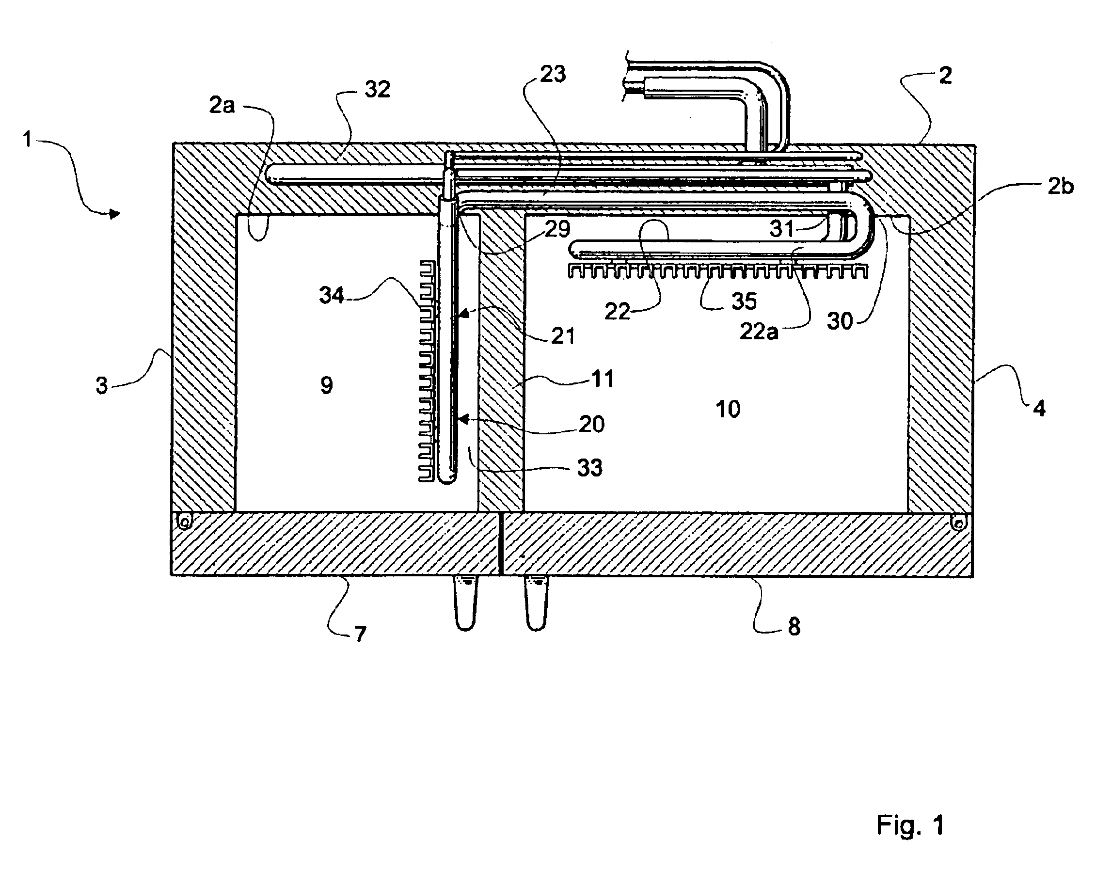
FIG. 1 is a top elevation view, with parts of the walls broken away, of a refrigerator cabinet according to the present invention.

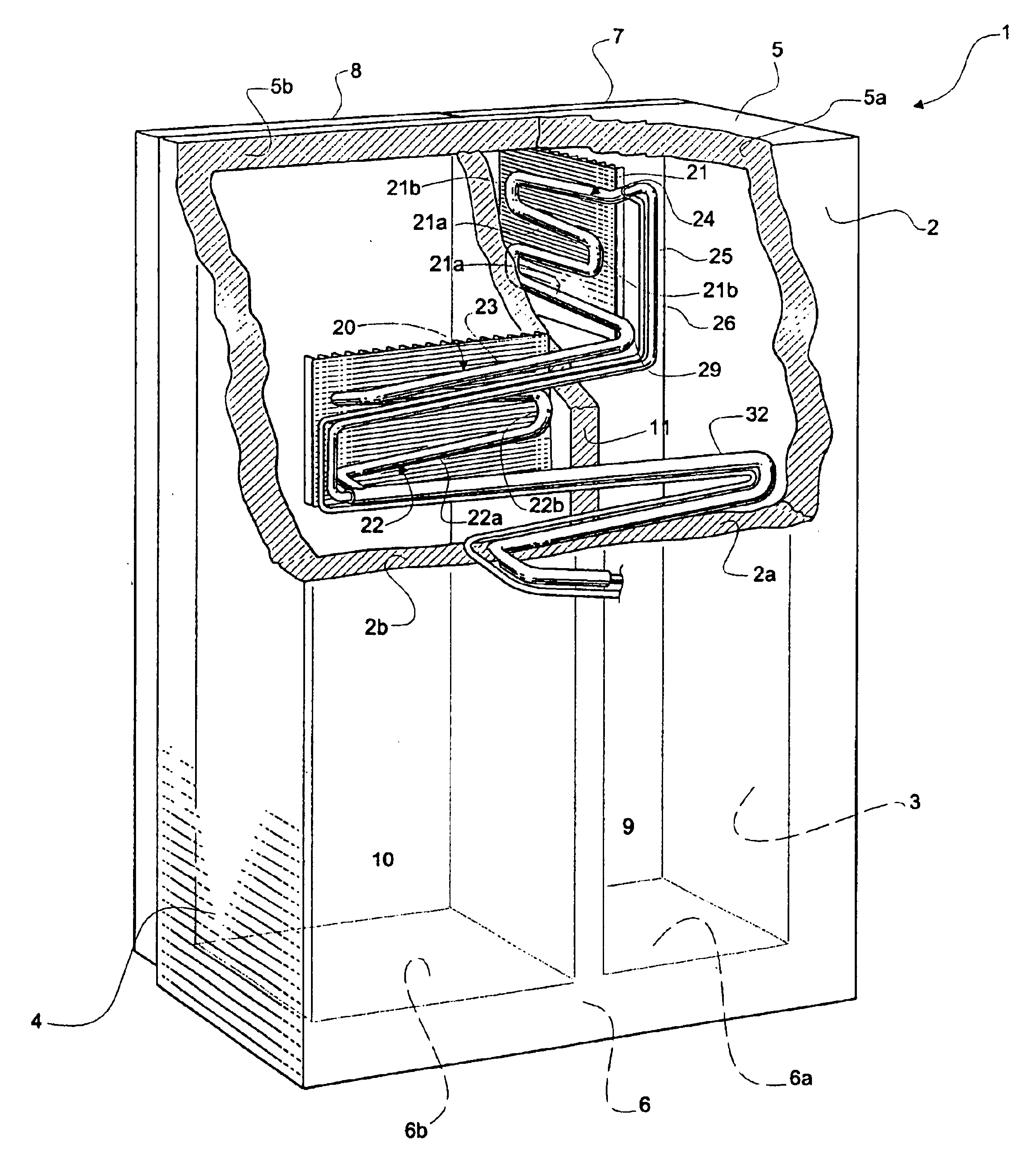
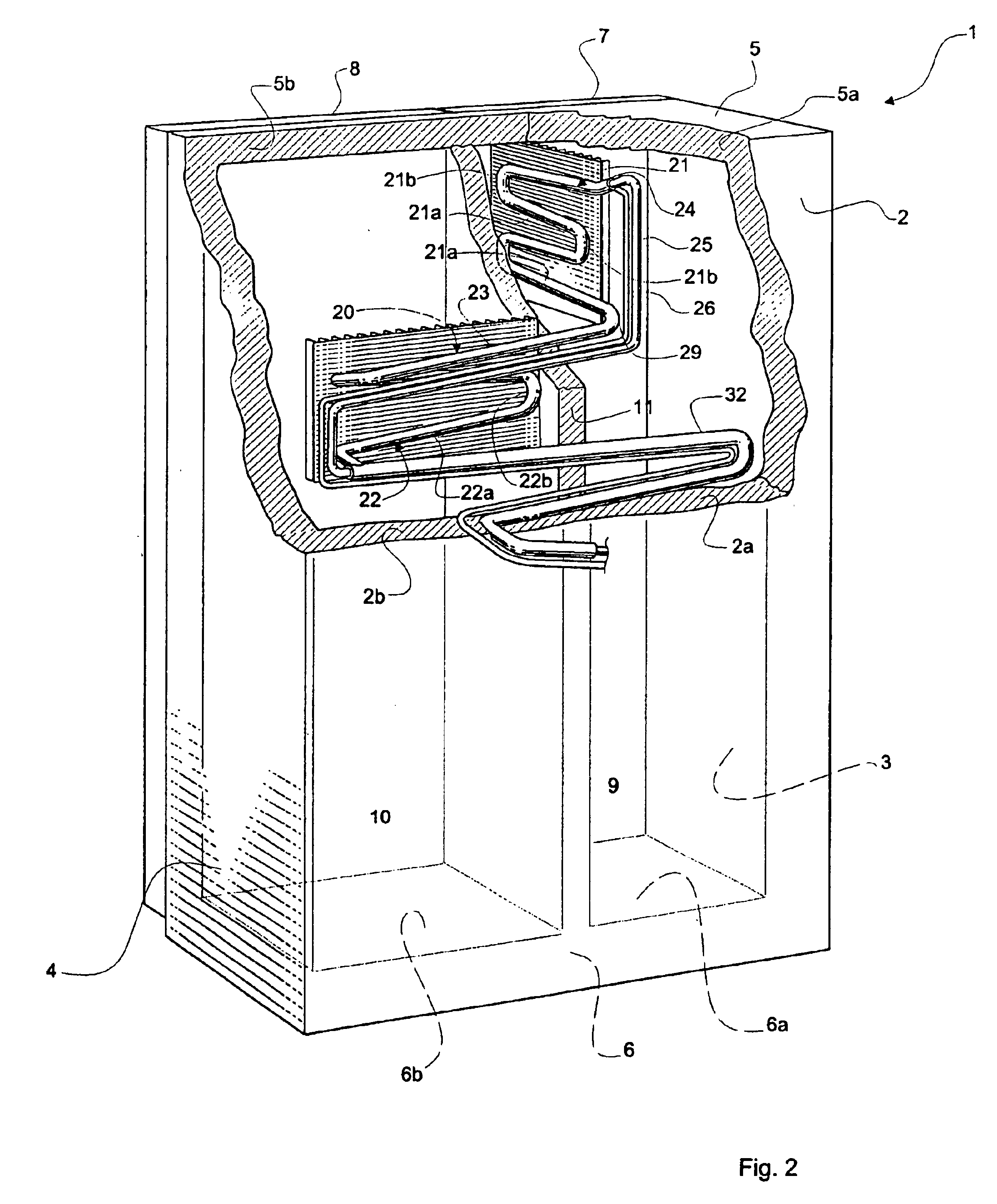
FIG. 2 is a perspective view from behind, with parts broken away, of the refrigerator in FIG. 1.

In the figures a side-by-side absorption refrigerator 1 is shown. The cabinet includes a rear wall 2, two side walls 3, 4, a top-wall 5 and a bottom-wall 6. These outer walls 2-6, together with two front doors 7, 8 enclose a low temperature storage compartment 9 and a higher temperature storage compartment 10. The outer walls 2-6 and the front doors 7, 8 all include an outer and an inner shell between which heat insulating material, such as polyurethane foam, is arranged. The two compartments 9, 10 are hermetically sealed from each a vertical partition wall 11, which extends perpendicular to and from the rear wall 2, between the rear wall 2 and...


PUM


Abstract

An absorption refrigerator (1) including a cabinet having outer walls (2, 3, 4, 5, 6) and at least one door (7, 8) encasing a low temperature storage compartment (9) and a higher temperature storage compartment (10), said compartments being essentially sealed from each other and separated by a partition wall (11), which partition wall is arranged inside the cabinet and generally perpendicular to a first wall (2) of said outer walls. The refrigerator further comprises an absorption refrigerating system including an evaporator tube (20), having a first section (21) for absorbing heat from the low temperature compartment and a second section (22) for absorbing heat from the higher temperature compartment, said second section being arranged downstream said first section. In order to reduce heat transfer into the cabinet through the outer walls, a major part of the first section is arranged generally in parallel with said partition wall.

Description

FIELD OF THE INVENTIONThe present invention relates to an absorption refrigerator including a cabinet having outer walls and at least one door encasing a low temperature storage compartment and a higher temperature storage compartment, said compartments being essentially sealed from each other and separated by a partition wall, which partition wall is arranged inside the cabinet and generally perpendicular to a first wall of said outer walls, and an absorption refrigerating system including an evaporator tube having a first evaporator tube section for cooling the low temperature compartment and a second evaporator tube section for cooling the higher temperature compartment, said second evaporator tube section being arranged downstream said first evaporator tube section.BACKGROUND OF THE INVENTIONAbsorption refrigerators have been commonly used in e.g. recreation vehicles and mobile homes for a long time. More recently, so called side-by-side absorption refrigerators have been increa...

Claims


Application Information

Patent Timeline
Patent Type & Authority Patents(United States)
IPC IPC(8): F25D11/02F25B39/02
CPCF25D11/027F25B39/026
Inventor HALLIN, ANDERS BENGT INGEMARKORNELIND, JOHNNY
Owner DOMETIC APPLIANCES
Learn More