Sensor mounting structure and semiconductor pressure sensor for motor vehicles

a technology of semiconductor pressure sensor and mounting structure, which is applied in the direction of instruments, heat measurement, machines/engines, etc., can solve the problems of increasing cost, increasing cost, and increasing both cost and labor

Inactive Publication Date: 2005-01-25
HITACHI LTD
View PDF9 Cites 40 Cited by
  • Summary
  • Abstract
  • Description
  • Claims
  • Application Information

AI Technical Summary

Benefits of technology

According to the above-described configuration, the sensor body (sensor housing) is formed simply by inserting the sensor holder having an electronic circuit section and a semiconductor gauge into the cap with the connector portion left outside, and the semiconductor gauge (pressure detector) housing section is located in the pressure inlet port, thereby enabling direct detection of a pressure without a pressure inlet pipe. Besides, the semiconductor gauge, if disposed directly into the part to be detected (e.g., the intake manifold), is protected by the cap positioned around the gauge, to thereby insure reliability of the pressure sensor.
In the configuration in which the pressure sensor is mounted directly on the pipe wall of the intake manifold with the pressure detector (gauge portion) exposed into the intake manifold, the pressure sensor has such a drawback that if the pressure inlet port is located horizontally or nearly horizontally, water generated as a result of sweating in the intake manifold enters the pressure inlet port and freezes to give damage to the gauge. However, when the gauge is disposed in the upper part of the pressure inlet port as stated in the above-described configuration, water caused by sweating will not enter the gauge. It is, therefore, possible to protect the gauge from damage resulting from icing.

Problems solved by technology

In the case of the synthetic resin manifold, it becomes necessary to form, by insert-molding, a metal part for receiving a mounting screw to fix a sensor housing at the time of molding the intake manifold, resulting in an increased cost.
It is also necessary to insert a metal bushing on the housing side to prevent biting and loosening of the screw, which also increases the cost.
This method, however, requires insertion of a spring member beside the sensor body into the sensor mounting section (cylindrical section), which will increase both cost and labor for assembling.
In this case also, it becomes necessary to form a cylindrical portion as the sensor mounting section, and to insert a spring member beside the sensor body into the sensor mounting section (cylindrical portion), resulting in an increased cost and labor for assembling.

Method used


Image

  • Sensor mounting structure and semiconductor pressure sensor for motor vehicles
  • Sensor mounting structure and semiconductor pressure sensor for motor vehicles
  • Sensor mounting structure and semiconductor pressure sensor for motor vehicles

Examples


Embodiment Construction

Preferred embodiments of the present invention will be explained with reference to the accompanying drawings of a semiconductor pressure sensor for one example.

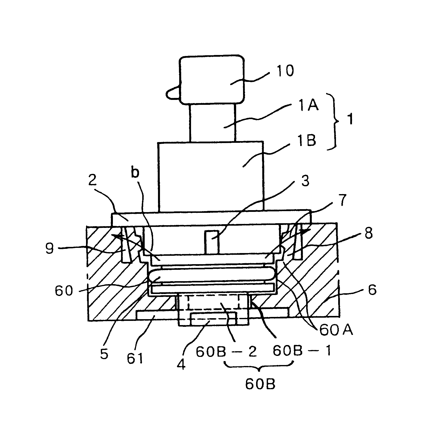
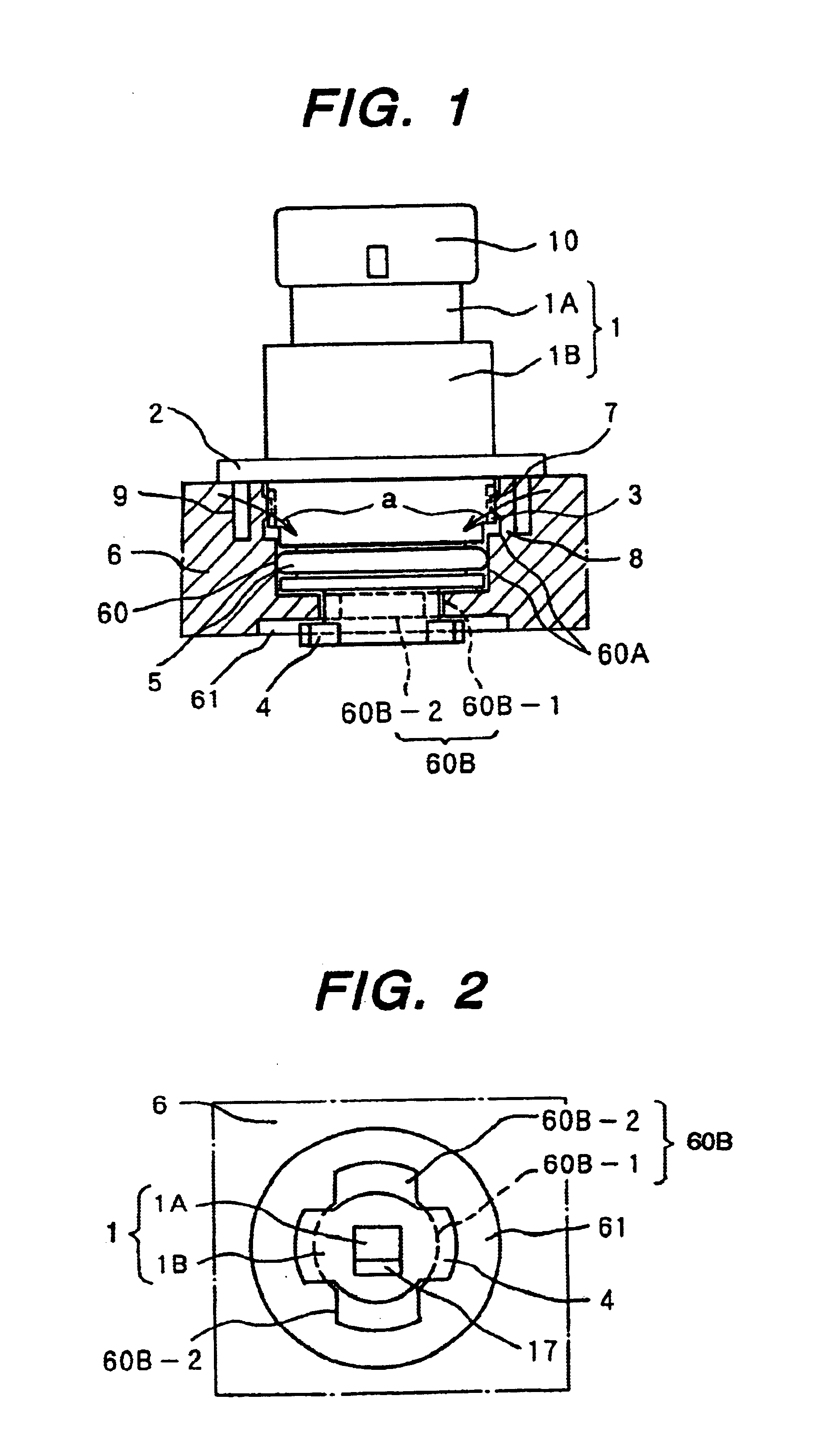
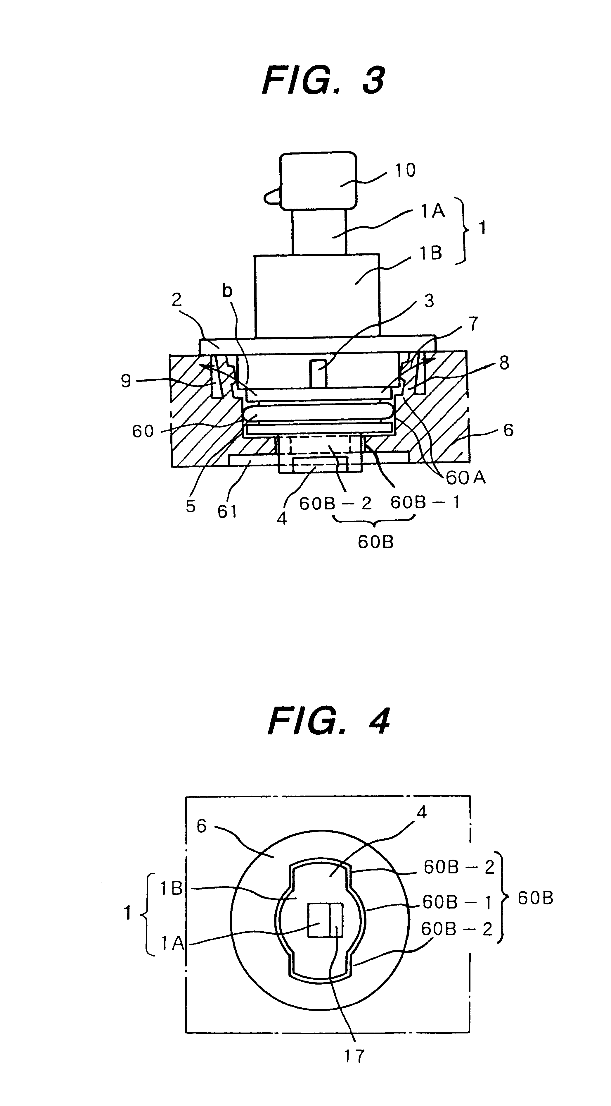
FIG. 1 is an explanatory view showing one embodiment of the sensor mounting structure according to the present invention, partly sectioned at the mounting hole made in an intake manifold of an internal-combustion engine for motor vehicles; FIG. 2 is a bottom vied thereof; FIG. 3 is an explanatory view showing the sensor on the way of mounting; FIG. 4 is a bottom view thereof; FIG. 5 is a longitudinal sectional view of the semiconductor pressure sensor; and FIG. 6 is a top view of the mounting hole in which the pressure sensor is fixed.

First, referring to FIGS. 1, 3 and 5, the structure of the overall housing which is the body of the semiconductor pressure sensor will be explained. The whole body of the housing 1 is separated largely into two parts as shown in FIG. 5; one is a sensor holder 1A including a connector 10, while t...


PUM

PropertyMeasurementUnit
specific angleaaaaaaaaaa
pressureaaaaaaaaaa
degree of freedomaaaaaaaaaa

Abstract

To provide a sensor mounting structure which enables mounting an automotive sensor directly to the wall section of a part to be detected, without using screws, and also mounting a pressure detector directly to a pressure air passage without using a pressure inlet pipe.The non-circular sensor mounting hole is provided for inserting a part of the sensor housing into the wall section of the part to be detected. In the sensor housing the first locking portion (pawl) and the second locking portion (flange) are integrally formed by molding. The housing 1 is allowed to be inserted into the mounting hole under the condition that the pawl is directed to a specific orientation, and, after insertion, is turned through a specific angle. Therefore the pawl is engaged on the inside surface of the wall section. The flange is engaged on the outside surface of the wall section. The pawl and the flange are designed to hold the wall section of the part to be detected, thereby mounting the sensor. The projection of the hook is engaged with the recess provided in the sensor housing 1, thus locking the sensor from turning.

Description

BACKGROUND OF THE INVENTIONThe present invention relates to a sensor mounting structure for mounting an automotive sensor (e.g., a pressure sensor, a temperature sensor, etc.) and a semiconductor pressure sensor to be used.There have been used various kinds of sensors for electronically controlling an internal-combustion engine mounted in a motor vehicle. These conventional sensors were attached by screws. For instance, as disclosed in Japanese Unexamined Patent Publication No. Hei 5-172673, brackets are attached in two places on a plastic molding housing to provide the pressure sensor mounting position with a degree of freedom of movement. The pressure sensor is attached by screws in an appropriate position through the bracket and the sensor section and a pressure source are connected by means of a hose.In recent years, a metal intake air passage, or a so-called intake manifold made of a metal, for use in the internal-combustion engine in motor vehicles is giving way to an intake m...

Claims


Application Information

Patent Timeline
Patent Type & Authority Patents(United States)
IPC IPC(8): G01L19/00G01L9/00G01L9/12G01K1/14
CPCG01L19/003G01L19/0007
Inventor MATSUMURA, TAKAFUMIMIYAZAKI, ATSUSHIYAMAGUCHI, SHINICHITANAKA, HIROYUKI
Owner HITACHI LTD
Why Eureka
Try Eureka