Surface mounted loudspeaker and bracket for the mounting thereof

a loudspeaker and surface mount technology, applied in the field of loudspeakers, can solve the problems of heat management problems, difficult to angle the loudspeaker for optimum sound quality and three-dimensional imaging, and reduce the ability to reposition the loudspeaker

Inactive Publication Date: 2005-01-25
BOSTON ACOUSTICS INC
View PDF4 Cites 27 Cited by
  • Summary
  • Abstract
  • Description
  • Claims
  • Application Information

AI Technical Summary

Benefits of technology

A slot may also be formed in the rear portion of the enclosure near at least one end of the enclosure and a corner bracket may be provided having an extension which fits snugly in the slot, the corner bracket, when the loudspeaker is corner mounted, filling the space between the rear surface of the enclosure and the corner. A slot may be formed at each end of the enclosure and a corner bracket provided for each such slot. The corner to bracket may also have a foot on one side, the foot when facing the adjacent end of the enclosure facilitating the standing of the loudspeaker on such adjacent end.

Problems solved by technology

While the latter two considerations sometimes result in the loudspeakers being flush mounted in for example a wall or ceiling, such mounting can be time consuming and expensive, significantly reduces the ability to reposition a loudspeaker if desired and can also result in heat management problems where the loudspeaker is in a confined space.
Flush mounting of a loudspeaker in a wall or ceiling may also make it difficult to angle the loudspeaker for optimum sound quality and three-dimensional imaging.
The former increases the cost of each unit shipped and also increases the size and weight of the product shipped, and therefore shipping costs.
The latter results in a requirement for stocking additional inventory and can result in inventory mismatch problems.
Much of the hardware currently used for surface mounting loudspeakers is also not well designed from an aesthetic standpoint, the brackets for example being substantially visible for the mounted loudspeaker, thus detracting from the overall aesthetics of the loudspeaker as mounted.
A further potential problem is that many of the brackets require that the loudspeaker be slid or fitted into the bracket by being moved in a direction having a substantial component parallel to the mounting surface.
This may limit the ability to mount the loudspeaker close to an adjacent ceiling, floor, or wall.
A final potential problem is that loudspeakers generally contain a name or logo plate of the manufacturer, which plate should have the same orientation on a mounted loudspeaker regardless of the loudspeaker orientation.

Method used


Image

  • Surface mounted loudspeaker and bracket for the mounting thereof
  • Surface mounted loudspeaker and bracket for the mounting thereof
  • Surface mounted loudspeaker and bracket for the mounting thereof

Examples


Embodiment Construction

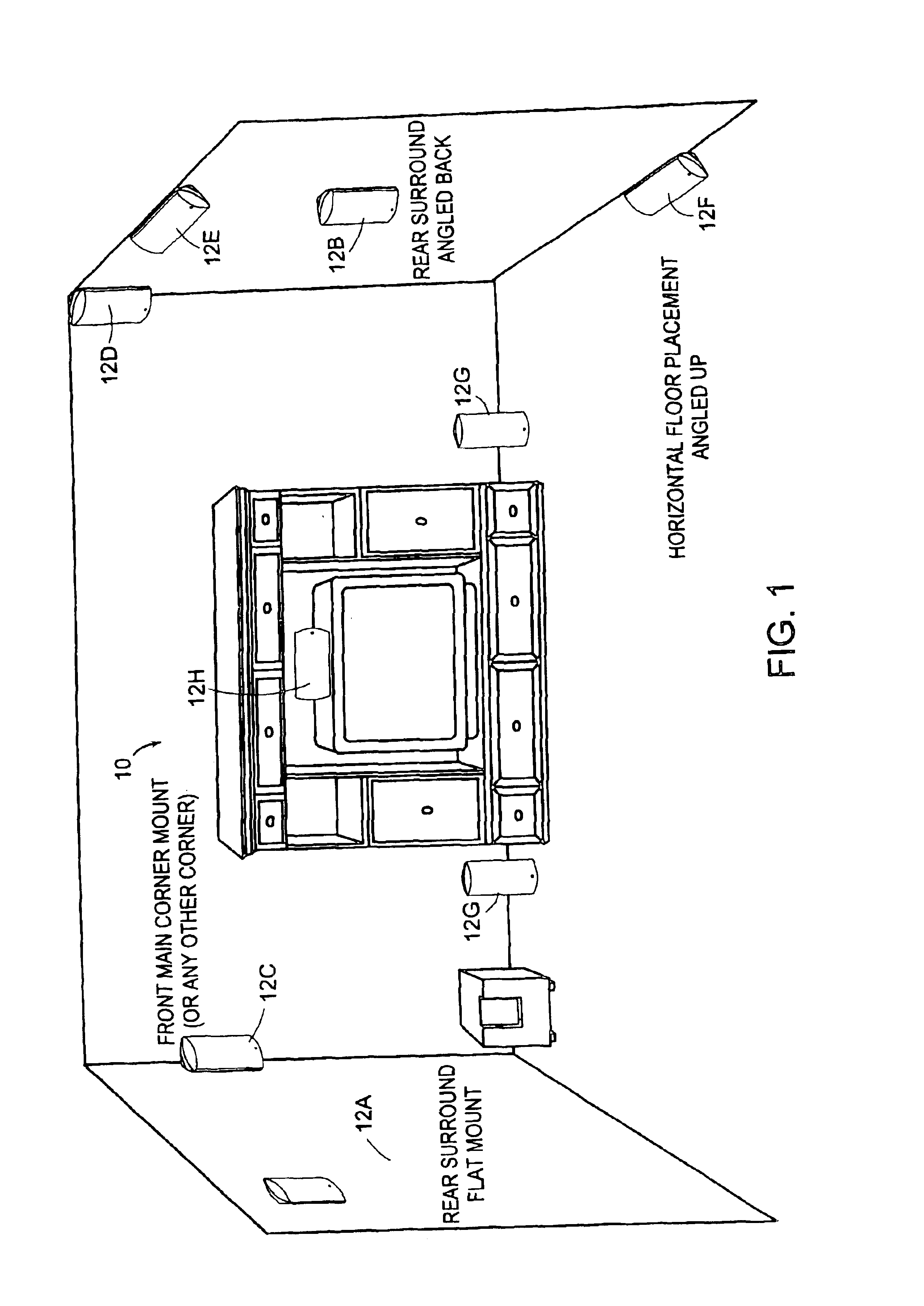
FIG. 1 illustrates a room containing a multimedia system 10 which includes a plurality of satellite speakers 12 positioned and angled throughout the room to achieve selected audio effects. It should be noted that the speakers shown in FIG. 1 are positioned and oriented to illustrate options available utilizing the teachings of this invention rather than for purposes of achieving a particular audio effect, and thus, while the various orientations shown are desirable for, and would be used in, various systems, the speakers 12 would probably not be combined as shown in FIG. 1 in a single system. In particular, speaker 12A is shown as a rear surround speaker flat-mounted to a wall (i.e. oriented so as to project perpendicular to the wall). Speaker 12B is a similar rear surround speaker mounted so as to be angled toward the back of the room (i.e. in the direction of the observer). Speakers 12C and 12D are front main corner-mounted speakers, speaker 12D being mounted at the junction of th...


PUM


Abstract

A surface mounted loudspeaker is provided which, in conjunction with a mating brace which fits in a recessed form in the rear of the speaker enclosure, is mountable to a single wall in a variety of orientations, in corners with various orientations, and to a substantially horizontal surface in a variety of orientations with little if any additional hardware. In all orientations, the speaker provides good aesthetics, with the bracket being substantially invisible.

Description

FIELD OF THE INVENTIONThis invention relates to loudspeakers and more particularly to a universal, surface-mounted loudspeaker having a mounting bracket and other components which facilitate the mounting or positioning of such loudspeaker on substantially any surface in a wide variety of orientations with good aesthetics.BACKGROUND OF THE INVENTIONAudio systems generally employ at least two and, particularly for surround sound applications, four or more loudspeakers. The positioning of these loudspeakers, while to some extent being dictated by desired audio performance, is also dictated by available space at the site where the audio system is located and by aesthetics. While the latter two considerations sometimes result in the loudspeakers being flush mounted in for example a wall or ceiling, such mounting can be time consuming and expensive, significantly reduces the ability to reposition a loudspeaker if desired and can also result in heat management problems where the loudspeake...

Claims


Application Information

Patent Timeline
Patent Type & Authority Patents(United States)
IPC IPC(8): F16M13/02H04R5/02
CPCF16M13/02F16M13/025H04R5/02
Inventor COWAN, JEFFREY N.PETRONIO, JAMESCHAMNESS, MICHAELHASKELL, CRAIG T.
Owner BOSTON ACOUSTICS INC
Why Eureka
Try Eureka