Piezoelectric element and injector using the same

a piezoelectric element and injector technology, applied in the direction of machine/engine, device details, machine/engine details, etc., can solve the problem that the organic insulating layer cannot positively block the moisture transmission, and achieve the effect of improving the performance of the piezoelectric element, reducing the size of the injector as a whole, and improving the radiation of hea

Inactive Publication Date: 2005-01-25
DENSO CORP
View PDF7 Cites 71 Cited by
  • Summary
  • Abstract
  • Description
  • Claims
  • Application Information

AI Technical Summary

Benefits of technology

The object of the present invention is to provide a highly reliable, compact, inexpensive piezoelectric element capable of achieving a good heat radiation characteristic without a shorting even in a very humid environment, and an injector using such a piezoelectric element.
According to the invention, therefore, a compact, high-performance injector can be provided.

Problems solved by technology

Nevertheless, the organic insulating layer cannot positively block the moisture transmission and allows the moisture in.

Method used


Image

  • Piezoelectric element and injector using the same
  • Piezoelectric element and injector using the same
  • Piezoelectric element and injector using the same

Examples


first embodiment

A piezoelectric element according to an embodiment of the invention will be explained with reference to FIGS. 1, 2 and 3a to 3c.

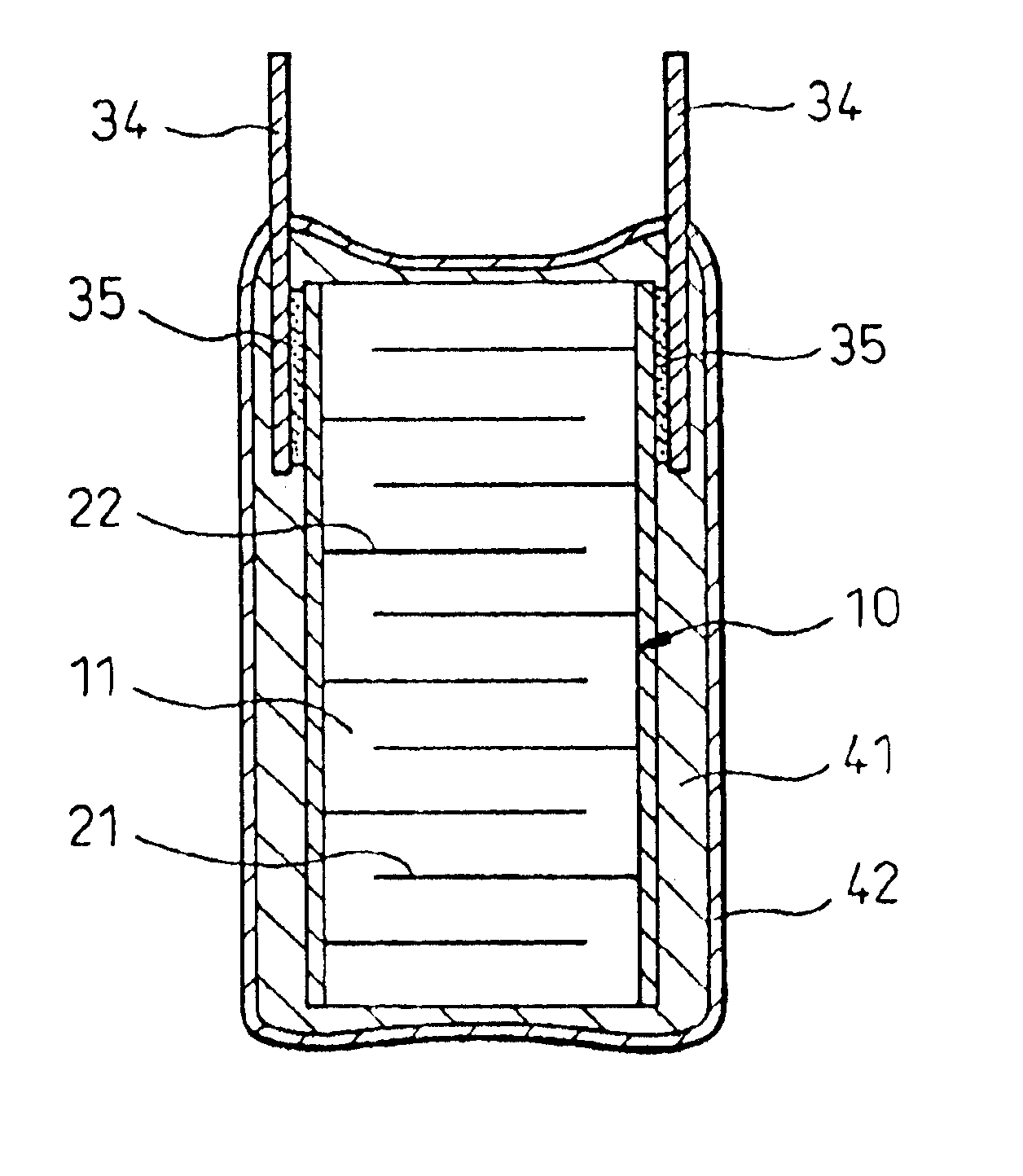
A piezoelectric element1 according to this embodiment comprises, as shown in FIG. 1, a ceramic laminate 10 including a plurality of ceramic layers 11 of a piezoelectric ceramic and internal electrode layers 21, 22 stacked alternately.

The piezoelectric element 1 further comprises at least an organic insulating layer 41 of an organic material formed on at least a part of the surface of the ceramic laminate 10, and at least an inorganic insulating layer 42 of an inorganic material formed above the organic insulating layer 41.

This configuration will be described in more detail below.

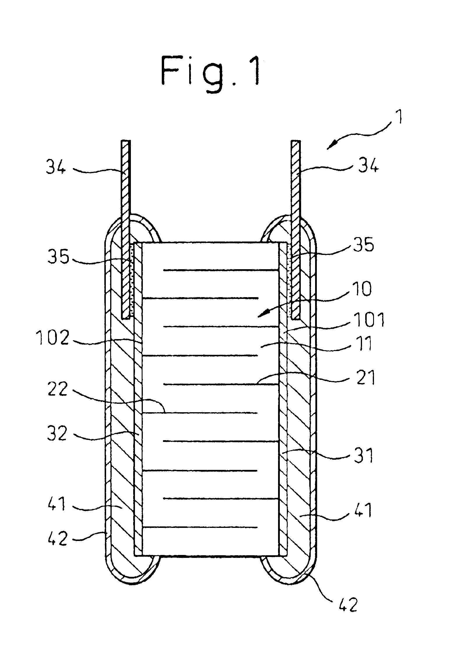
The ceramic laminate 10 of the piezoelectric element 1 is configured, as shown in FIGS. 2 and 3a to 3c, in such a manner that the internal electrode layers 21, 22 are formed to assume alternately positive and negative polarities between the ceramic layers 11. As shown in FIGS. 2 an...

second embodiment

This embodiment represents an example of an injector 5 configured so that a valve is operated using the displacement of the piezoelectric element 1 according to the first embodiment thereby to control fuel injection.

The injector 5 according to this embodiment is used with a common rail injection system for the diesel engine as shown in FIG. 4.

The injector 5, as shown in FIG. 4, comprises an upper housing 52 for accommodating the piezoelectric element 1 constituting a drive unit, and a lower housing 53 fixed on the lower end of the upper housing 52 and formed with an injection nozzle portion 54 therein.

The upper housing 52 is substantially cylindrical in shape, and has a longitudinal hole 521 eccentric of the center axis thereof through which the piezoelectric element 1 fixedly inserted.

A high-pressure fuel path 522 is arranged in parallel with the side of the longitudinal hole 521. The upper end portion of the fuel path 522 communicates with an external common rail (not shown) throu...

third embodiment

The piezoelectric element 1 according to this embodiment, as shown in FIG. 7, represents a case in which all the surfaces including the end surfaces along the direction of stacking as well as the side surface of the ceramic laminate 10 are covered with the organic insulating layer 41 and the inorganic insulating layer 42. The other points are similar to those of the first embodiment.

In this case, moisture intrusion can be prevented more securely. The other operation and effects are similar to those of the first embodiment.


PUM

PropertyMeasurementUnit
total thicknessaaaaaaaaaa

Abstract

A piezoelectric element and an injector using the same piezoelectric element are disclosed, which are so high in reliability as not to be shorted even in a high humidity environment, are small in size, are low in cost and are high in heat radiation capability. The piezoelectric element comprises a ceramic laminate (10) including a plurality of ceramic layers of a piezoelectric ceramic (11) and a plurality of internal electrode layers (21, 22), stacked alternately. At least an organic insulating layer (41) of an organic material is formed on at least a part of the surface of the ceramic laminate (10), and at least an inorganic insulating layer (42) of an inorganic material is formed on the organic insulating layer (41).

Description

BACKGROUND OF THE INVENTION1. Field of the InventionThe present invention relates to a piezoelectric element used for a piezoelectric actuator and an injector using the piezoelectric element.2. Description of the Related ArtIn recent years, the piezoelectric element used as a piezoelectric actuator has begun to employ a laminated structure generally comprising 100 to 700 piezoelectric ceramic layers as thin as 20 to 200 μm and a plurality of internal electrode layers composed of a metal, which are stacked alternately in order to produce a large displacement with a low voltage.The internal electrode layers each have an end portion thereof exposed to the side surface of the laminate, and there is the possibility of shorting between the internal electrode layers. Various countermeasures have been taken.As an example, an organic material is arranged on the side surface of the laminate as an insulating structure. Although an organic material has an insulating effect in a normal air atmos...

Claims


Application Information

Patent Timeline
Patent Type & Authority Patents(United States)
IPC IPC(8): F02M59/00F02M59/46F02M47/02H01L41/083H01L41/00H01L41/04F02M51/06H01L41/09
CPCF02M47/027F02M63/0026H01L41/083H01L41/0533H01L41/0833H10N30/883H10N30/503H10N30/50
Inventor SATO, KAZUHIDETERA, RYONOSUKEKAWAZOE, NAOYUKI
Owner DENSO CORP
Why Eureka
Try Eureka