Torus-shaped mechanical gripper

a mechanical gripper and torus-shaped technology, applied in the direction of hoisting equipment, load-engaging elements, thin material handling, etc., can solve the problems of no torus-shaped membrane as the gripping mechanism, and difficult to hold onto

Inactive Publication Date: 2005-01-25
RAGNER GARY DEAN +1
View PDF5 Cites 185 Cited by
  • Summary
  • Abstract
  • Description
  • Claims
  • Application Information

AI Technical Summary

Problems solved by technology

Furthermore, none were found that use a torus shaped membrane as the gripping mechanism.
This toy is noted for its very slippery rolling action that makes them hard to hold onto.

Method used


Image

  • Torus-shaped mechanical gripper
  • Torus-shaped mechanical gripper
  • Torus-shaped mechanical gripper

Examples


Embodiment Construction

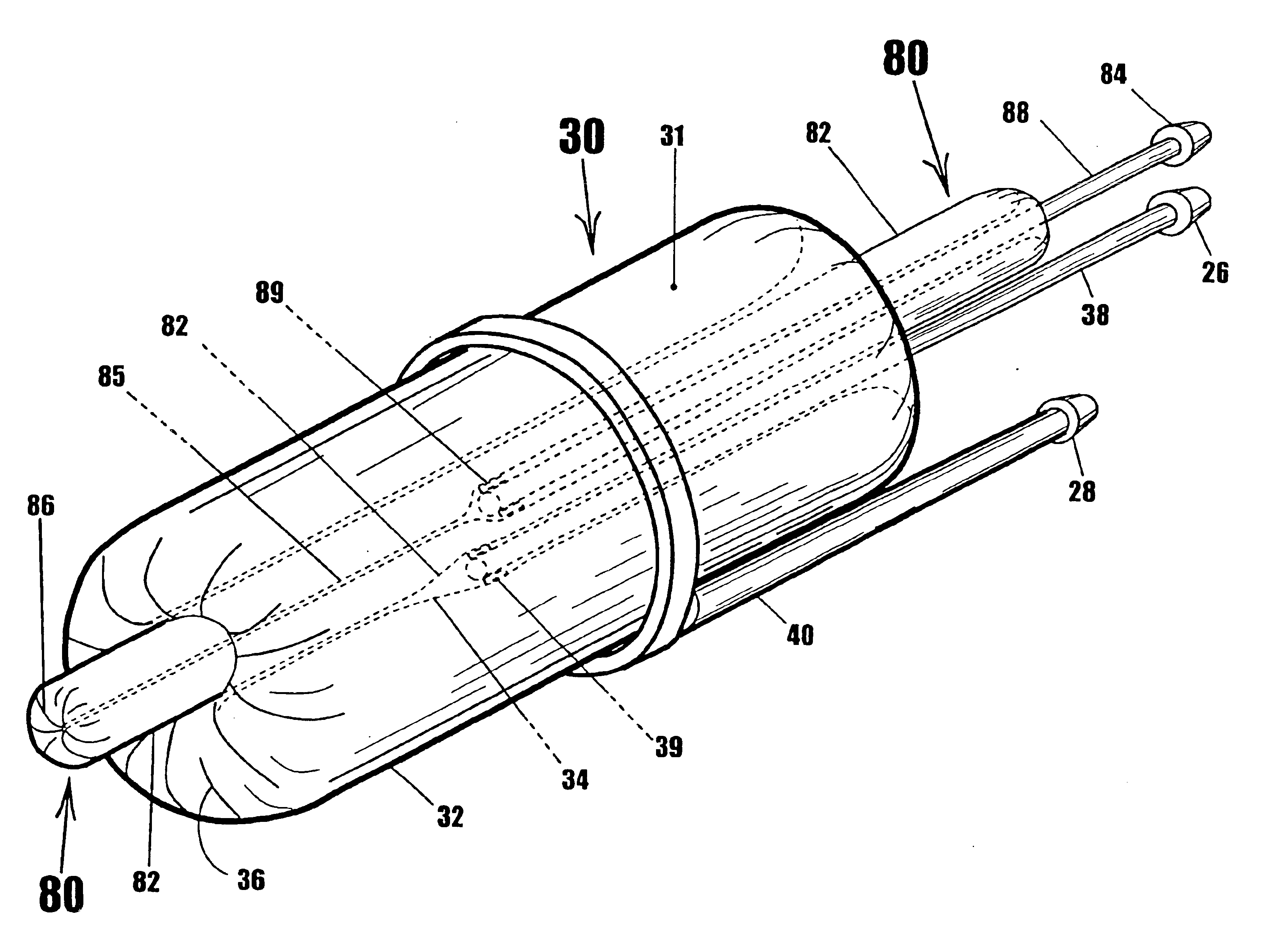
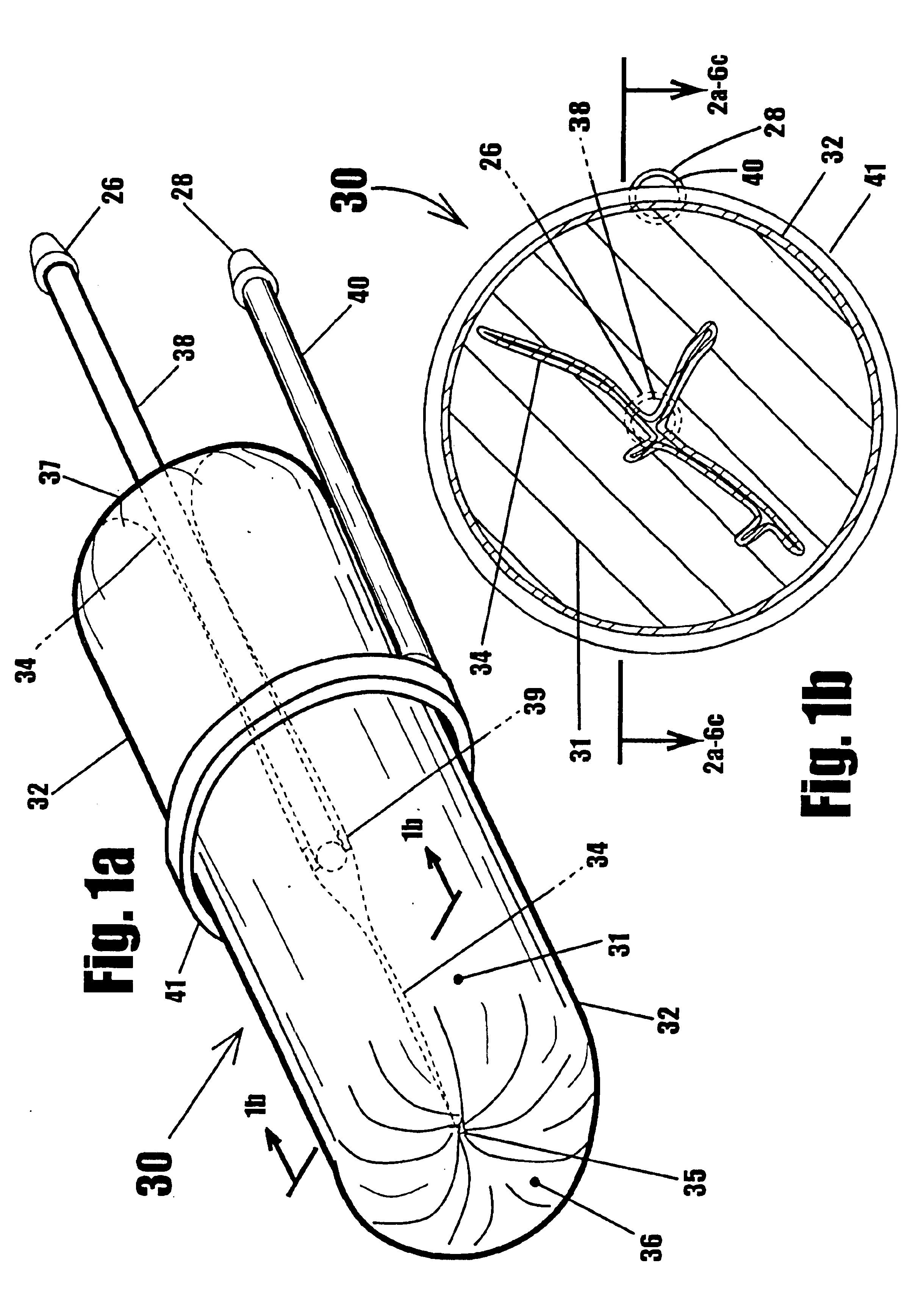
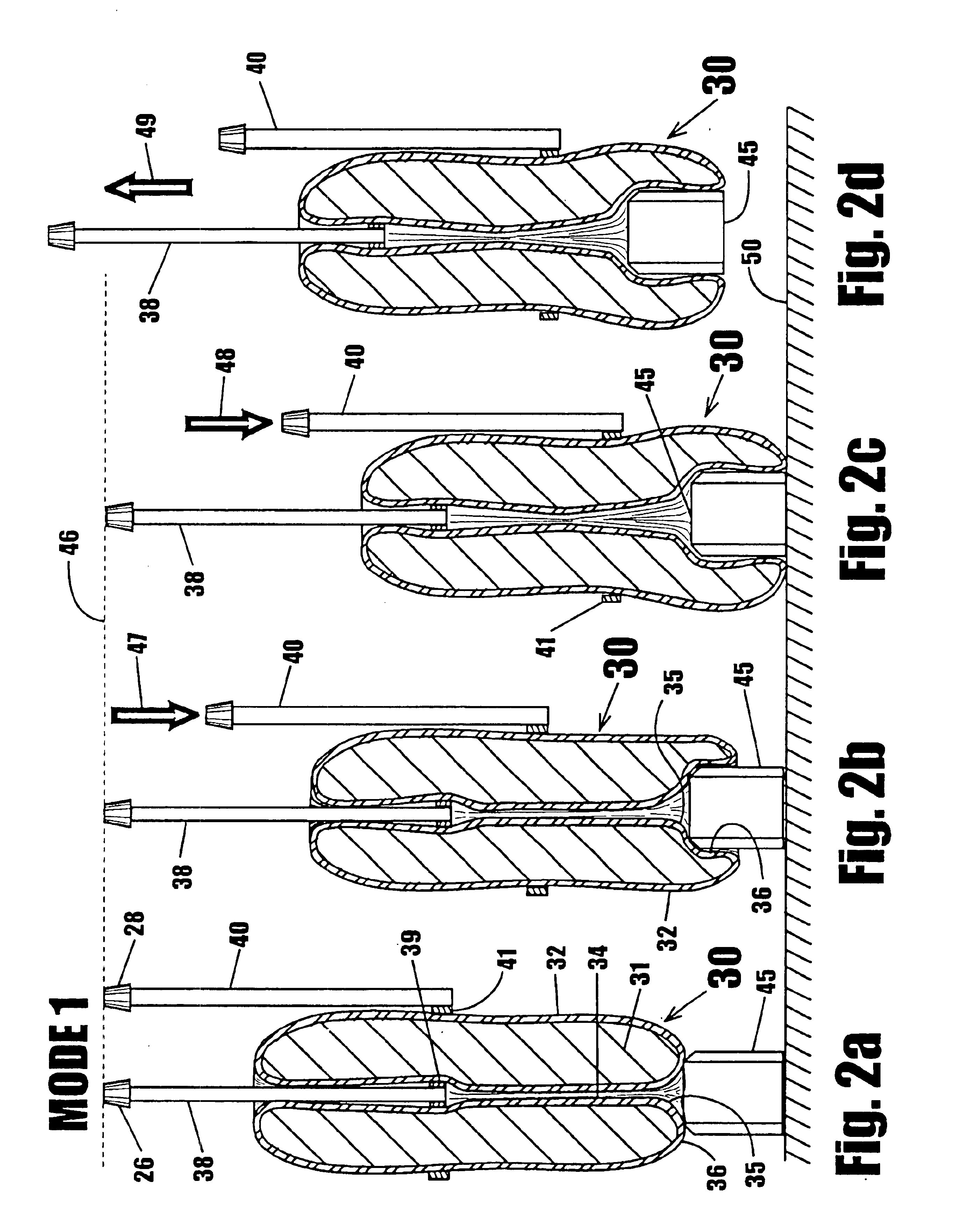
In FIG. 1a we see a simple robotic gripper comprising of an elongated torus 30, and a pair of control rods 38 and 40. Torus 30 is made of a stretchable membrane material such as rubber, latex, or other stretchable material which allows the membrane to be rotate around its interior volume. Torus shaped membrane 30 is made sufficiently flexible to allow collapsed channel portion 34 of the torus to be rotation to the expanded exterior surface 32 of the torus. Torus 30 has a high coefficient of friction to help it grip objects, and comprises an exterior section 32, a collapsed interior portion 34, and end transition portions 36 and 37. Torus 30 can be manufactured in a number of way, including: 1) blow molding—where rubberized plastic is expanded in a torus shaped mold, 2) spin molding—where liquid polymer is put in a torus shaped mold and rotated to coat all the surfaces of the mold, 3) single weld—using a single tube of stretchable material and threading one end through the tube to th...


PUM


Abstract

A device for gripping, holding, and releasing objects of varying sizes and shapes, which comprises an elongated torus (30) enclosing a fluid material (31), an external control rod (40), and an internal control rod (38). Torus (30) may be made of a flexible membrane and able to seal in fluid material (31). Fluid material (31) can be a gas, liquid, solid particles, semisolid particles, or mixtures of these. Central channel (34) of torus (30) is collapsed due to pressure of fluid material (31) within torus (30). Both control rods are securely attached to torus (30), with rod (38) attached to the interior portion of the torus along collapsed central channel (34), and rod (40) attached to the exterior portion of the torus on outer surface (32). Gripping action is achieved by differential linear motion of control rods (38) and (40) along the longitudinal (elongated) axis of torus (30). This causes front portion (36) of the torus to slide radially inward or outward to grip objects. Further movement of the control rods can cause the object to be pulled completely inside the collapsed channel for secure gripping by completely surrounding the object. The soft flexible nature of torus (30) allows grasping even the most delicate objects without damaging them. Even over-ripe strawberries can be rapidly grasped without bruising.

Description

BACKGROUNDThis invention pertains to mechanical gripping devices that can grip and release objects by mechanical control and more specifically to mechanical gripping devices that grip by radial sliding-action gripping surfaces.BACKGROUND—DESCRIPTION OF PRIOR ARTThe use of grippers on robotic arms has existed for the last few decades, as robots have become more common in factories and other businesses. These grippers or robotic hands are used by robotic arms to grip objects and perform functions such as moving objects, inserting parts, sorting parts, and etc. Prior art shows many types and styles of mechanical grippers (or hands), most of which use fingers or claws to grab and hold objects. No references were found that used radial sliding contacts for gripping, holding, and releasing object like the disclosed invention. Furthermore, none were found that use a torus shaped membrane as the gripping mechanism. Such three-dimensional rotating structures appear to be completely novel to ...

Claims


Application Information

Patent Timeline
Patent Type & Authority Patents(United States)
IPC IPC(8): B25B9/00B25J15/00B25J15/12B65G47/90
CPCB25B9/00B25J15/0023B25J15/12B65G47/905B65G47/908Y10S294/907B65G2201/0202B65G2201/0211B65G2203/041
Inventor RAGNER, GARY DEANKINNEY, WILLIAM ROSS
Owner RAGNER GARY DEAN
Why Eureka
Try Eureka