Apparatus for continuous stirring and process for continuous polycondensation of polymer resin

a technology of polymer resin and apparatus, which is applied in clay mixing apparatus, rotary stirring mixers, transportation and packaging, etc., can solve the problems of degrading the quality of the resulting liquid product, and achieve the effect of enhancing the degree of polymerization and low polymerization

Inactive Publication Date: 2005-01-25
HITACHI LTD
View PDF8 Cites 19 Cited by
  • Summary
  • Abstract
  • Description
  • Claims
  • Application Information

AI Technical Summary

Benefits of technology

An object of the present invention is to solve the problems of the above prior arts, and to provide an apparatus for continuously stirring a viscous material, applicable to liquid feeds ranging from a low viscosity to a high viscosity to obtain the resulting liquid product of good quality and also a process for continuous polycondensation of polymer resin.
In the present invention, a polymer resin having a low degree of polymerization is continuously supplied as a liquid feed into the vessel of the apparatus for continuous stirring from the inlet and stirred by rotating the two rotating blade assemblies in the direction opposite to each other, while moving the liquid feed towards the outlet, thereby conducting good surface renewed to evaporate the volatile matters and enhance the degree of polymerization.

Problems solved by technology

The apparatus of U.S. Pat. No. 3,964,874 is suitable for stirring and mixing a liquid feed having a low viscosity, but in the case of a liquid feed having a higher viscosity than about a few hundred Pa•s, the stagnant high viscosity liquid feed deposited on the rotating shaft surfaces are liable to rotate together with the rotating shafts, so that the stagnant high viscosity liquid feed are highly susceptible to heat deterioration, etc., resulting in degrading of the quality of the resulting liquid product.

Method used


Image

  • Apparatus for continuous stirring and process for continuous polycondensation of polymer resin
  • Apparatus for continuous stirring and process for continuous polycondensation of polymer resin
  • Apparatus for continuous stirring and process for continuous polycondensation of polymer resin

Examples


Embodiment Construction

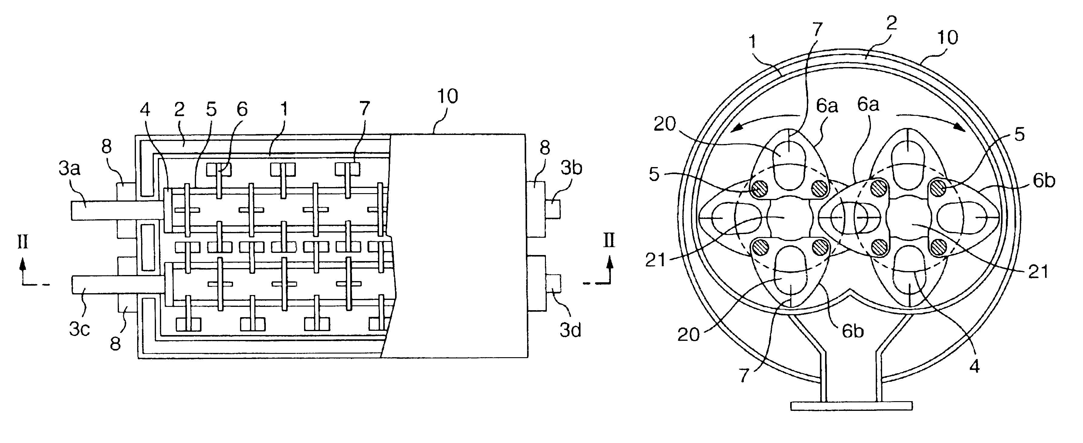
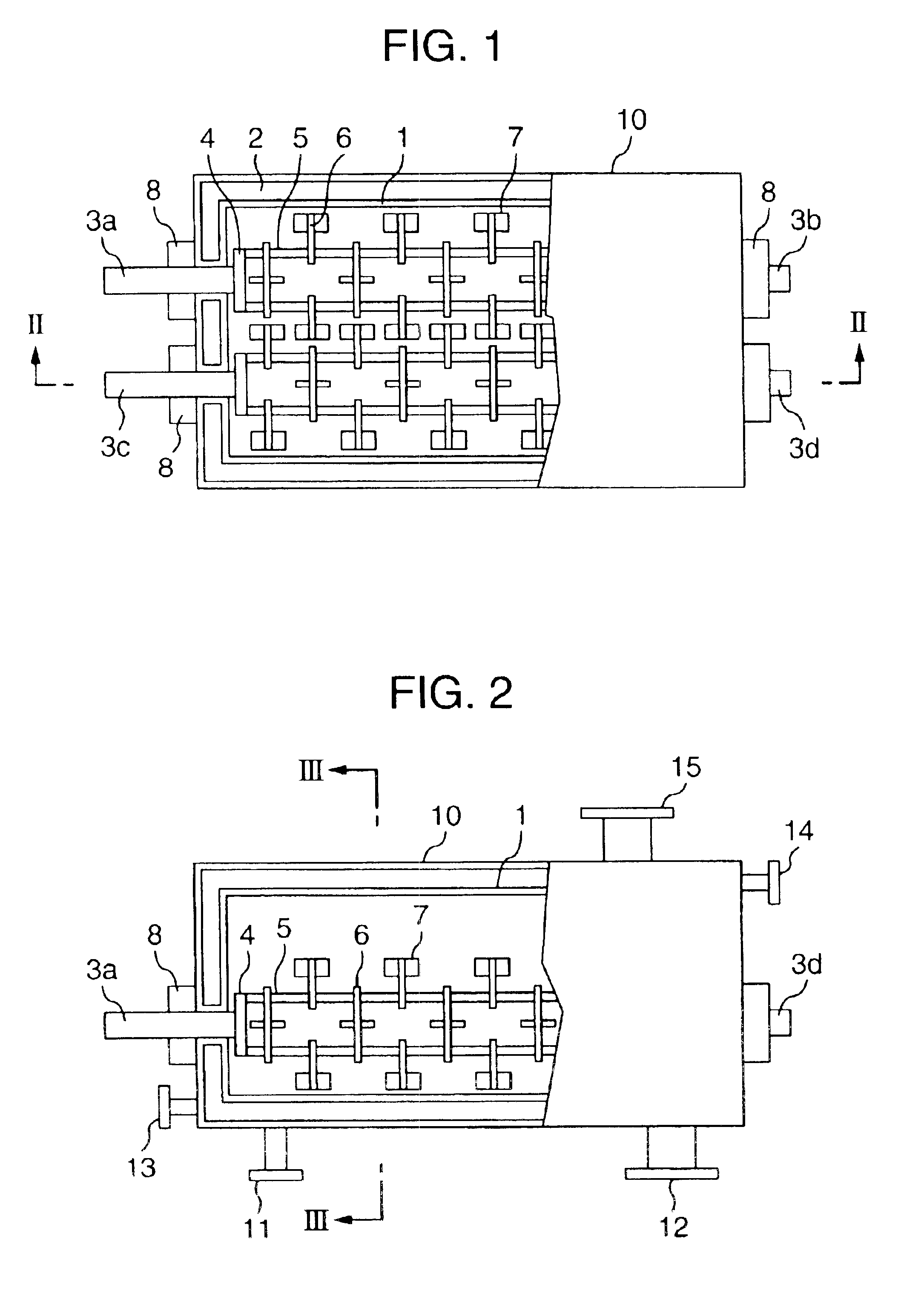
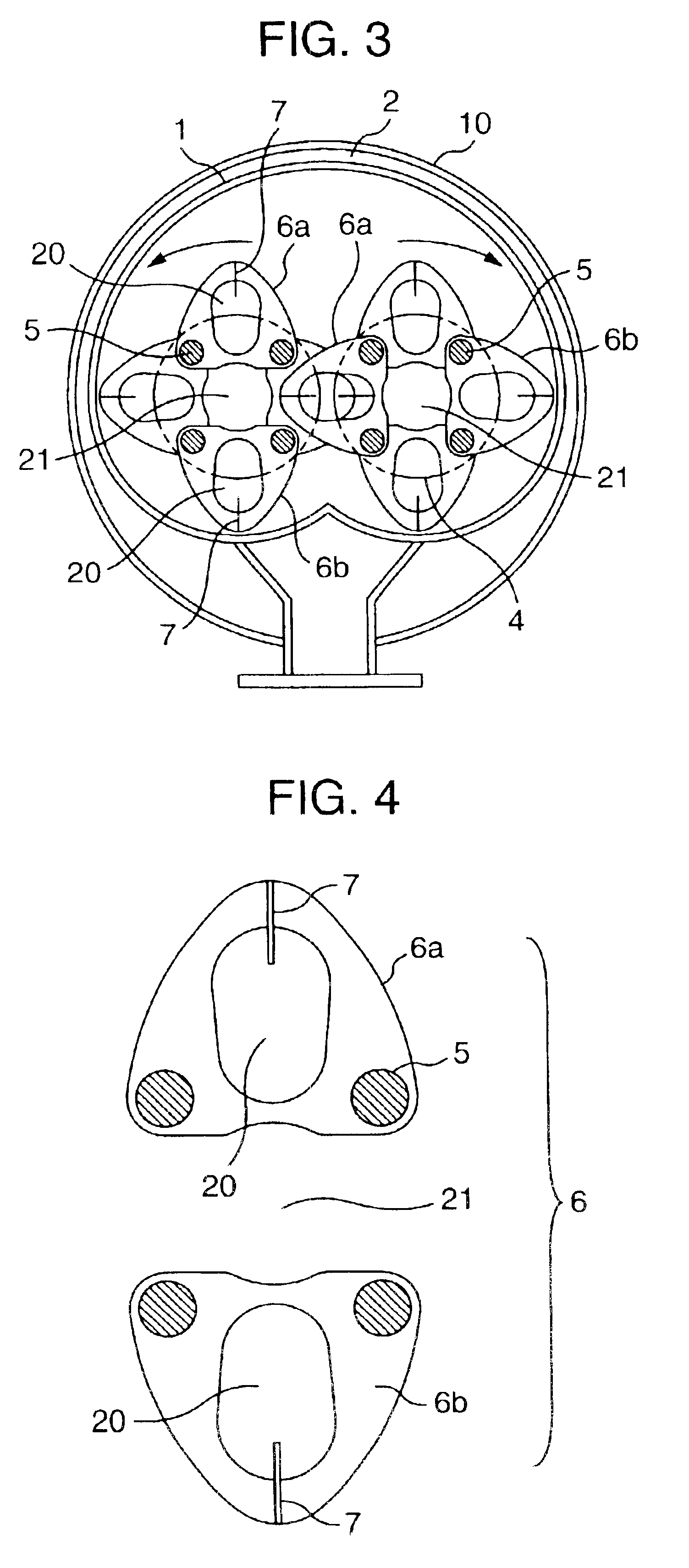
Embodiments of the present invention will be described below, referring to FIGS. 1 to 4.

As shown in FIGS. 1 and 2, stirring apparatus proper 10 comprises a horizontal elongated cylindrical vessel 1 having a cross-section as shown in FIG. 3, provided in a horizontal direction of the apparatus 10, whose outer periphery is covered by heating medium jacket (heater) 2, to which a heating medium is supplied to heat the vessel 1. Through each of both ends in the longitudinal direction of the horizontal elongated cylindrical vessel 1 are penetrated two pairs of first rotor shafts 3a—second rotor shaft 3b, and first rotor shaft 3c—second rotor shaft 3d, each being supported in a rotatable manner by bearing 8, while the first rotor shaft 3a and the first rotor shaft 3c are each connected to a rotation driver provided outside the vessel 1 so that they can be driven to undergo synchronized rotation in the direction opposite to each other. First and second disk-shaped support members 4 are fixed...


PUM

PropertyMeasurementUnit
phase angleaaaaaaaaaa
viscosityaaaaaaaaaa
viscosityaaaaaaaaaa

Abstract

An apparatus for continuous stirring comprising a horizontal elongated cylindrical vessel and two rotating blade assemblies rotatable in the direction opposite to each other provided in parallel to each other in the vessel, where a liquid feed is moved from one end to another therethrough by rotation of the two rotating blade assemblies in the direction opposite to each other, while stirring and mixing the liquid feed, the two rotating blade assemblies each comprising rotor shafts (3a-3b or 3c-3d) supported at both ends of the rotating blade assemblies, support members (4) each fixed to the rotor shafts, connecting members (5) span between the support members (4) and in positions far from the substantial rotating shaft center and a plurality of plate-shaped stirring blades (6) arranged in parallel in the longitudinal direction of the substantial rotating shaft center and fixed to the connecting members (5).

Description

BACKGROUND OF THE INVENTION1) Field of the InventionThe present invention relates to an apparatus and a process for stirring highly viscous materials, and more particularly to an apparatus for continuous stirring, suitable for continuous polycondensation or stirring, mixing or degassing of polycondensation series polymers (polymer resin) such as polyethylene terephthalate, polycarbonate, etc., and a process for continuous polycondensation of polymer resin.2) Related ArtHorizontal elongated cylidrical apparatuses for continuous stirring or continuous treatment 8polycondensation, etc.) of polyethylene terephthalate, etc. have been so far disclosed in U.S. Pat. No. 4,776,703 (JP-A-62-112624), JP-A-3-239727 or U.S. Pat. No. 3,964,874 (JP-A-48-102894).U.S. Pat. No. 4,776,703 discloses an apparatus for continuous treatment of a highly viscous material, which comprises a horizontal elongated cylindrical vessel and two rotating blade assemblies each comprising support rotors provided each a...

Claims


Application Information

Patent Timeline
Patent Type & Authority Patents(United States)
IPC IPC(8): B01F15/00B01F7/02B01F7/04C08G63/00C08G64/00C08G64/20C08G63/78B01F7/00C08G85/00
CPCB01F7/00208B01F7/00583B01F7/042B01F7/043C08G85/006C08G63/785C08G64/205B01F7/003B01F2215/0427B01F2215/0472B01F2215/0481B01F2215/0495B01F2215/0468B01F27/091B01F27/11251B01F27/13B01F27/703B01F27/702C08G63/78
Inventor OKAMOTO, NARUYASUMOTOHIRO, SEIJIITOU, YUKIKAHARADA, SUSUMU
Owner HITACHI LTD
Why Eureka
Try Eureka