
Threaded intraosseous dental implant

a dental implant and intraosseous technology, applied in the field of dental implants, can solve the problems of insufficient implant lifetime, inconvenient implant fitting, and inability to achieve the desired postoperative primary stability, and achieve the effect of increasing the primary stability of fitted implants

Inactive Publication Date: 2005-01-25
MIB GMBH +1
View PDF6 Cites 33 Cited by
  • Summary
  • Abstract
  • Description
  • Claims
  • Application Information

AI Technical Summary

Benefits of technology

In view of these shortcomings of the dental implants known to date, it is an object of the invention to propose an implant form which contributes to increasing the primary stability of fitted implants so that the implant is immediately able to bear loads, both during the postoperative work involved in attaching the superstructures and also during use by the patient. Immediate ability to bear loads signifies the primary stability achieved immediately after implantation. However, it will be appreciated that in some cases it is advantageous to wait several days of the main wound-healing phase before actual loading of the implant. Moreover, an optimized implant form is intended to maintain the natural introduction of force into the bone, comparable to that in a real tooth, and thereby to guarantee the long-term success to a greater extent.
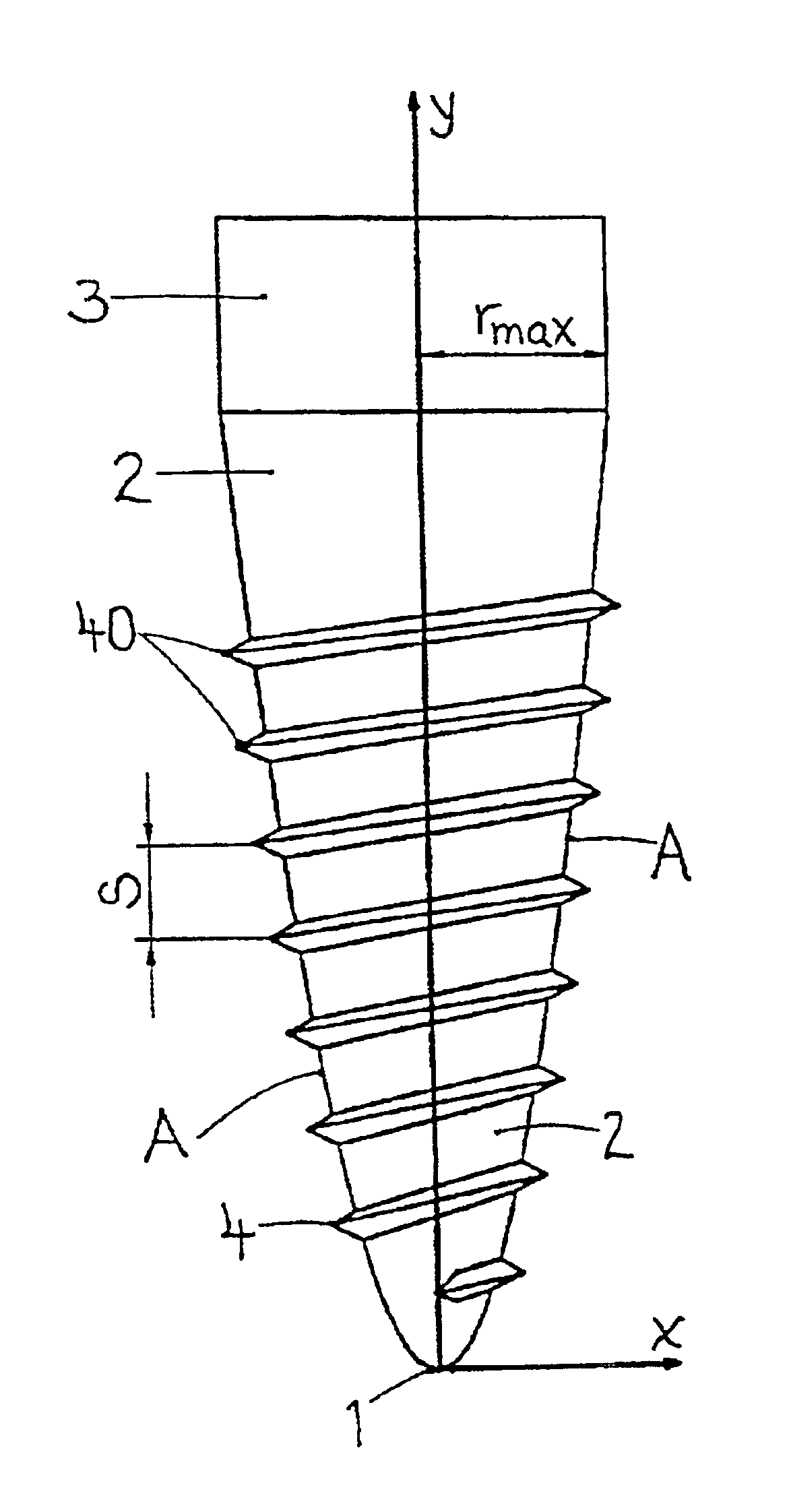
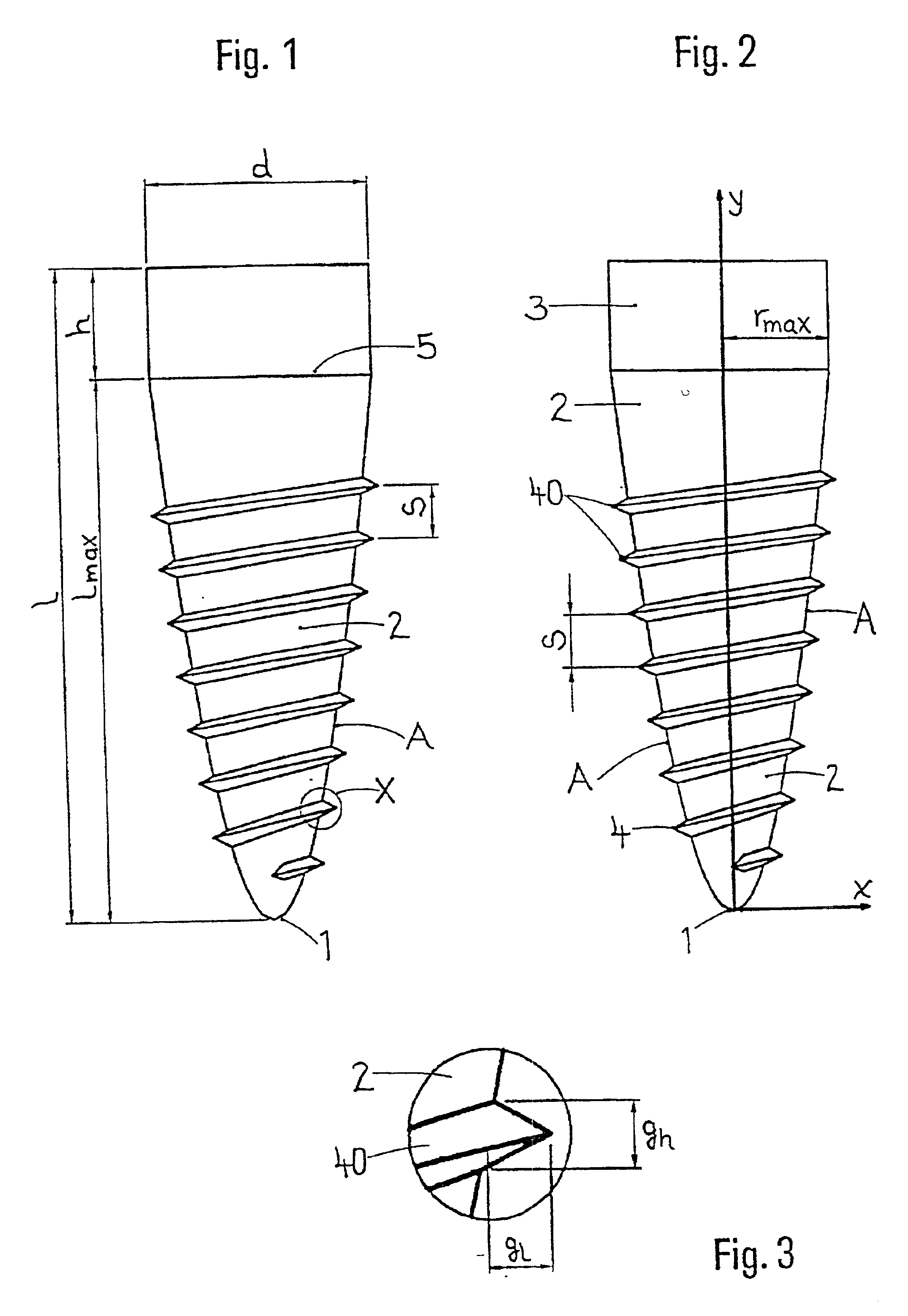
The maximum radius rmax is between 1.0 mm and 3.0 mm; it preferably lies in the range of from 1.5 mm to 2.0 mm. The maximum length lmax of the root part correlates with the pitch of the outer thread, the latter ending at a distance from the ridge line. The distance is preferably 1.0 mm to 4.0 mm. This distance is defined by the thickness of the cortical zone on the marginal bone and by the length of the implant. In order to guarantee an optimum introduction of force into the bone in this area, the distance of the outer thread from the ridge line becomes greater as the length of the root increases. In addition, the distance contributes to excluding the very critical entry of bacteria into the implant bed.

Problems solved by technology

The basically cylindrical shape of the root part has proven not best suited for obtaining the desired postoperative primary stability of the fitted implant.
Moreover, the lifetime of the implants is in many cases inadequate: the fitted implant loosens early after just a few years.
Investigations revealed that this early loosening is caused by bone resorption around the fitted implant, which is attributable to insufficient introduction of force to the bone via the existing implant forms.
Values below 1000 microstrains are considered inadequate and result in reduced mineralization and formation of connective tissue.
Values above 4000 microstrains are considered excessive and result in bone resorption (see Barbier, L. et al.

Method used


Image

  • Threaded intraosseous dental implant
  • Threaded intraosseous dental implant

Examples


Embodiment Construction

There follows a detailed description of an illustrative embodiment of the dental implant according to the invention, with reference to the attached drawings.

At the very bottom of the implant is the apically situated implant tip 1 to which the root part 2 extends from the coronal direction, which root part 2 is intended to be fitted in the jawbone. Adjoining the top of the root part 2, at the theoretical ridge line 5, is the implant neck 3 which extends in the coronal direction and is intended to lie inside the gingiva. From the implant tip 1 to a point below the ridge line 5, the root part 2 is provided with an outer thread 4 which is preferably self-cutting and has the pitch S. The outer thread 4 ends at a distance below the ridge line 5; the distance is preferably in the range of from 1.0 mm to 4.0 mm. The root part 2 has a substantially parabolic outer contour A with the implant tip 1 as vertex.

The following dimensions can be defined on the implant:l→total length, for example 12....


PUM


Abstract

The screw-type intraossal dental implant has a bottommost implant tip that is located in the apical area and comprises a root part which extends up to said implant tip and which is intended for insertion into a jaw bone. The implant neck extending up to the coronal area is placed on the root part and is intended for being placed inside the gingivae. The outer thread on the root part is preferably self-cutting. The invention is characterized in that the root part comprises an essentially parabolic outer contour with the implant tip serving as the vertex. The inventive outer contour makes it possible to obtain an improved primary stability and guarantees, to a great extent, the long-term success of the implant.

Description

FIELD OF APPLICATION OF THE INVENTIONThe present invention relates to a dental implant which is intended to be fitted in the jawbone and which has a thread on its outside. To this extent, the implant according to the invention differs generically from blade and cylinder implants as the other forms of intraosseous dental implants. In particular, the invention concerns the outer geometry of the implant, the measurement ratios of the implant body, and the characteristics of the outer thread, with the object of improving both primary and secondary stability and of thereby guaranteeing the long-term success of fitted implants.PRIOR ARTAlthough this invention concerns dental implants, the shorter form “implant” will be used hereinafter for the sake of brevity. An overview of the implant forms commonly used in dentistry is given by H. Spiekermann in “Implantologie, Farbatlanten der Zahnmedizin” published by Georg Thieme Verlag Stuttgart and New York, 1994, vol. 10, page 15. Here, a differe...

Claims


Application Information

Patent Timeline
IPC IPC(8): A61C8/00A61B17/58
CPCA61C8/0022A61C8/0018
Inventor JOOS, ULRICH
Owner MIB GMBH
Learn More