

Transfer case shift system for controllable bi-directional overrunning clutch
a transmission case and shift system technology, applied in the direction of interengaging clutches, couplings, gearing, etc., can solve the problems that the controllable overrunning clutch assembly does not always provide the required durability or predictable vehicle handling characteristics for use in modern four-wheel drive vehicles, and achieves significant axial length reductions.
- Summary
- Abstract
- Description
- Claims
- Application Information
AI Technical Summary
Benefits of technology
Problems solved by technology
Method used
Image

Examples
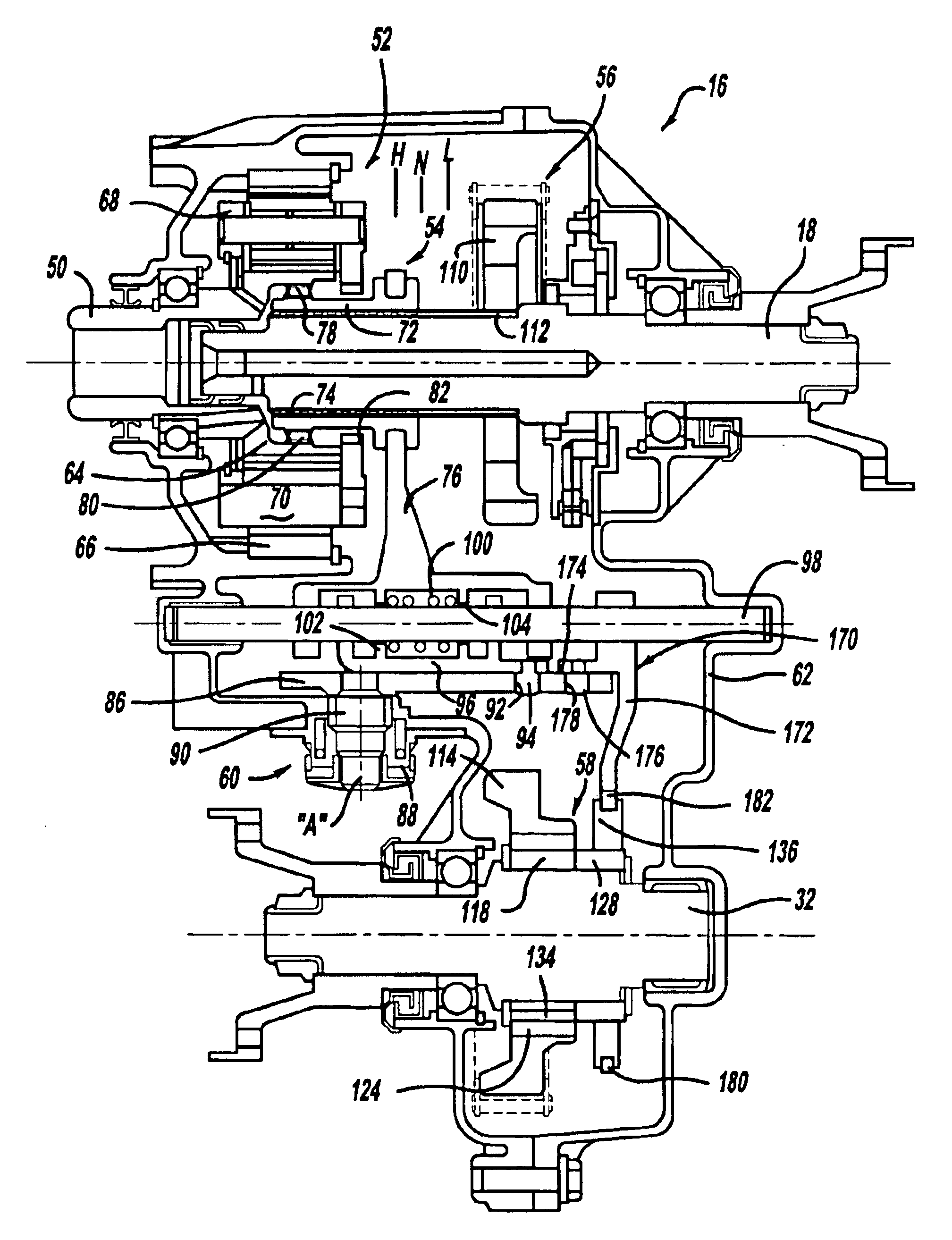
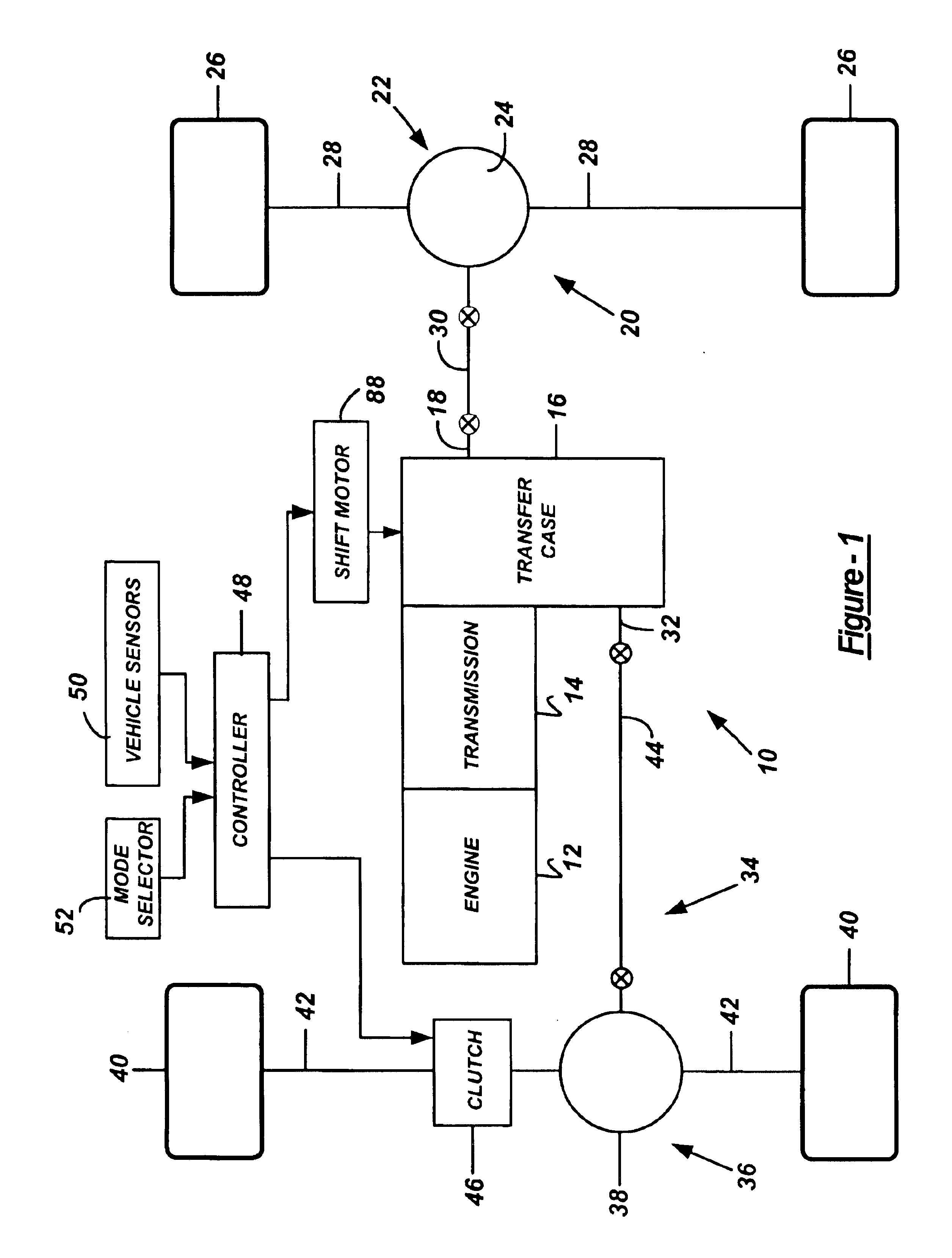
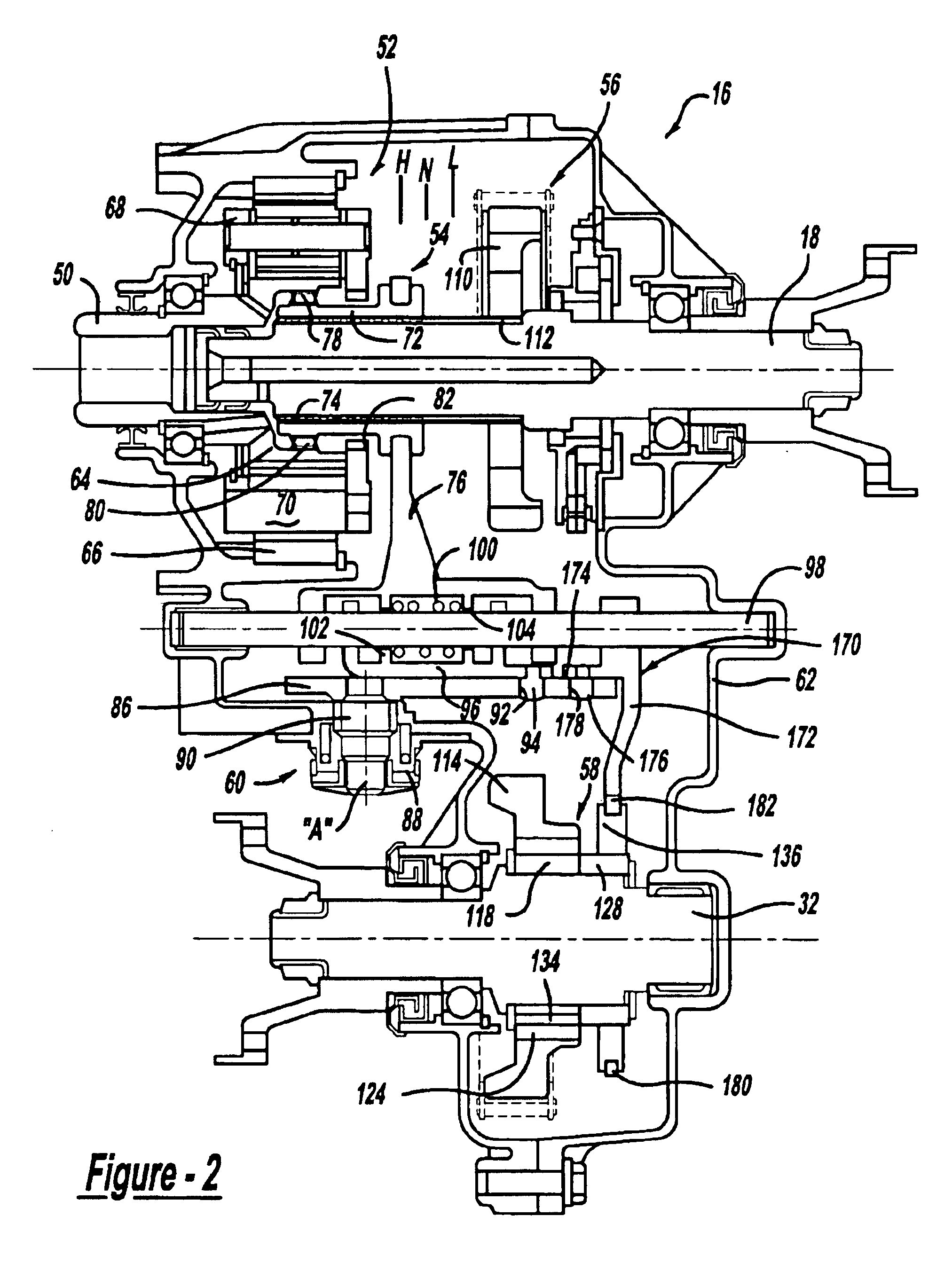
case 16
Transfer case 16 further includes a secondary output shaft 32 that is operably connected to a secondary driveline 34. Secondary driveline 34 includes an axle assembly 36 having a differential 38 driving a pair of wheel assemblies 40 via axleshafts 42, and a driveshaft 44 connected between secondary output shaft 32 and differential 38. An axle disconnect clutch 46 is provided for selectively coupling axleshafts 42 to differential 38. When disconnect clutch 46 is released, secondary driveshaft 44 and secondary output shaft 32 are disconnected from the remainder of secondary driveline 34 and are not rotatably driven by rolling movement of wheels 40. Alternatively, locking hubs (not shown) may be used to selectively couple and uncouple wheels 40 from connection with axleshafts 42.
Drive system 10 also includes an electronic controller 48 which receives input data from various vehicle sensors 50 and a mode selector 52. Controller 48 uses the input data from sensors 50 and mode selector 52...
PUM
 Abstract
Description
Claims
Application Information