Welding contact tip and diffuser

a contact tip and diffuser technology, applied in the field of welding apparatus, can solve problems such as twisted welding wires, and achieve the effects of quick and easy assembly, quick and easy disassembly, and reduced hea

Inactive Publication Date: 2005-01-25
VICTOR EQUIP
View PDF33 Cites 45 Cited by
  • Summary
  • Abstract
  • Description
  • Claims
  • Application Information

AI Technical Summary

Benefits of technology

Among the several objects of this invention may be noted the provision of an improved contact tip and diffuser which are designed for quick and easy assembly, without using threads and without requiring the use of tools; the provision of such an assembly which provides quick and easy disassembly without requiring removal of the nozzle of the welding apparatus and without the need for substantial turning or twisting of the contact tip; the provision of such an assembly which, in some embodiments, provides a dual locking mechanism for maintaini...

Problems solved by technology

However, this type of connection requires turning of the contact tip and diffuser relative t...

Method used


Image

  • Welding contact tip and diffuser
  • Welding contact tip and diffuser
  • Welding contact tip and diffuser

Examples


Embodiment Construction

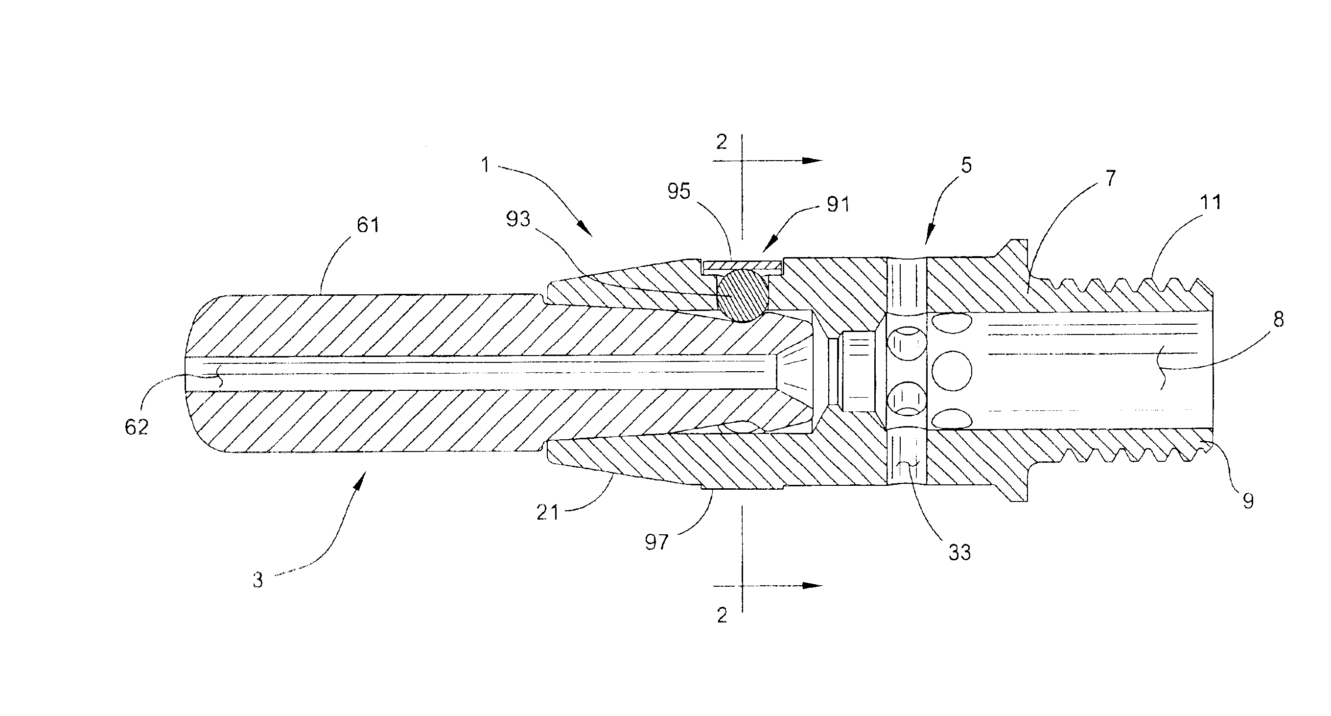
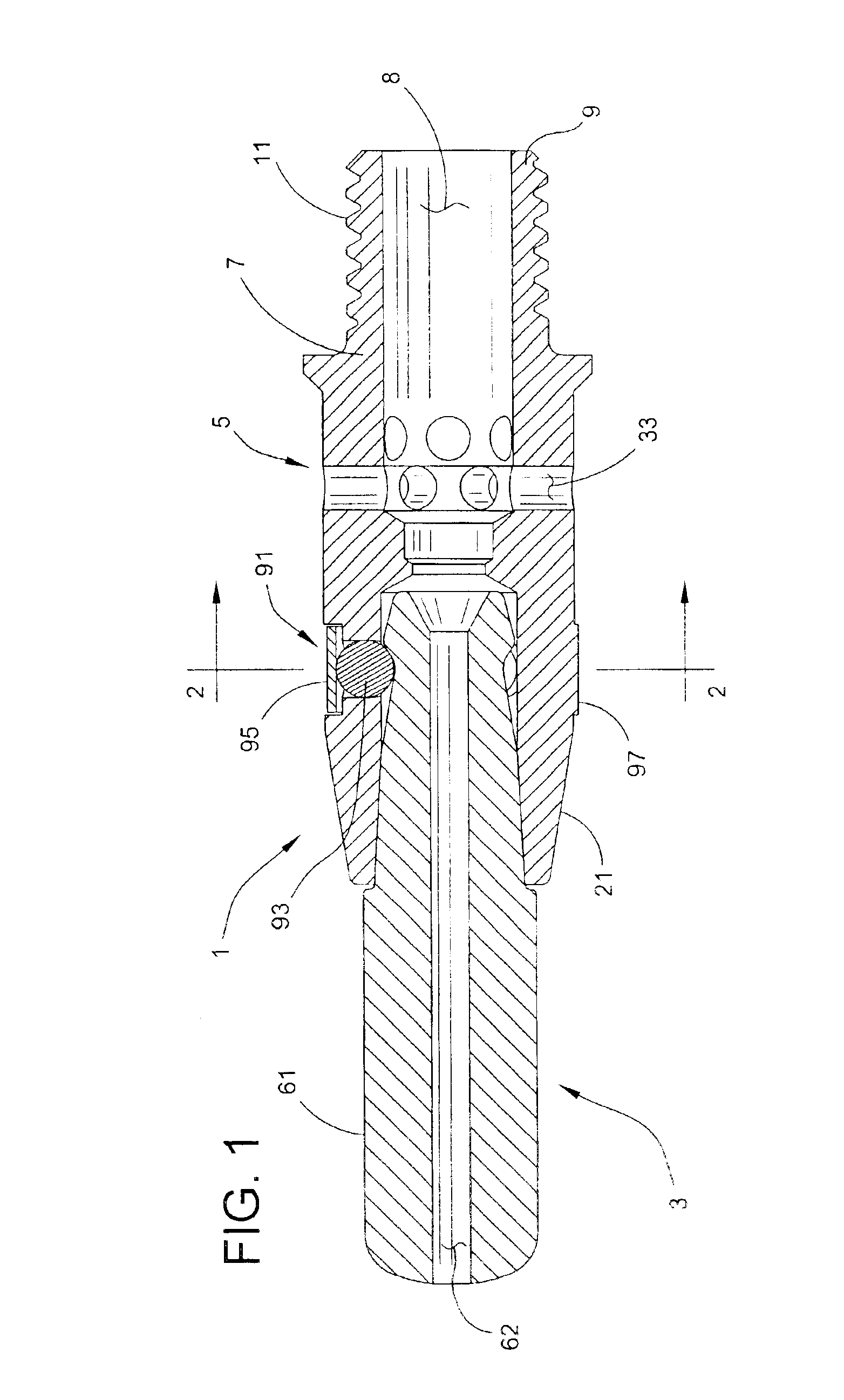
Referring now to the drawings, and first more particularly to FIG. 1, a contact tip and diffuser assembly of the present invention is designated in its entirety by the reference numeral 1, the contact tip being generally designated 3 and the diffuser generally designated 5. This assembly is used in the operation of welding apparatus, typically a MIG welding gun which may be either hand-held or automated. Reference may be made to U.S. Pat. No. 5,338,917, incorporated by reference herein for all purposes, for a disclosure relating to such MIG welding apparatus. It will be understood, however, that the teachings of this invention can be used with other types of cutting, gouging and / or welding equipment.

As shown in the drawings and particularly FIGS. 4 and 5, the diffuser 5 of one embodiment of this invention comprises an elongate diffuser body 7 having a longitudinal axis A1, a back end 7A, a forward end 7B, and a central bore 8 extending from the back end to the forward end allowing f...


PUM

PropertyMeasurementUnit
Angleaaaaaaaaaa
Forceaaaaaaaaaa
Electrical conductivityaaaaaaaaaa

Abstract

A welding contact tip and diffuser assembly for use in a welding apparatus. The assembly includes an electrically conductive contact tip having a tapered exterior surface, a diffuser having a cavity with a tapered interior surface, and a releasable connection for holding the contact tip in the diffuser. The connection includes at least one detent element in either the diffuser or the contact tip, at least one recess forming a ramp in the other of the diffuser or contact tip, and at least one spring. The spring biases the detent element into the recess and against the ramp to generate an axial force against the ramp. The axial force tends to urge the tapered surfaces of the contact tip and diffuser into contact with one another.

Description

BACKGROUND OF THE INVENTIONThis invention relates generally to welding apparatus, and more particularly to contact tips and diffusers for MIG welding guns and the like.This invention represents an improvement over prior connections between a contact tip and the diffuser of a MIG welding gun or automated welding equipment. A typical connection is a threaded connection of the type shown in U.S. Pat. Nos. 5,760,373 and 6,307,179, both of which are incorporated by reference herein for all purposes. However, this type of connection requires turning of the contact tip and diffuser relative to one another, which is often inconvenient, time-consuming and may result in twisted welding wire.SUMMARY OF THE INVENTIONAmong the several objects of this invention may be noted the provision of an improved contact tip and diffuser which are designed for quick and easy assembly, without using threads and without requiring the use of tools; the provision of such an assembly which provides quick and eas...

Claims


Application Information

Patent Timeline
IPC IPC(8): B23K9/173B23K9/24B23K9/12B23K9/29
CPCB23K9/122B23K9/295B23K9/173B23K9/26
Inventor STUART, KYLELONGHOFER, RONDELL L.
Owner VICTOR EQUIP
Why Eureka
Try Eureka