Field assembly and methods for assembling a field assembly

a field assembly and assembly method technology, applied in the field of electric motors, can solve the problems of difficult to achieve the cross-over of the winding support over the winding support using standard winding machinery, and the connection between the terminal assembly and the end of the winding is not as stabl

Inactive Publication Date: 2005-01-25
MILWAUKEE ELECTRIC TOOL CORP
View PDF21 Cites 27 Cited by
  • Summary
  • Abstract
  • Description
  • Claims
  • Application Information

AI Technical Summary

Benefits of technology

One independent advantage of the present invention is that the field assembly may be used to manufacture motor assemblies having different polarities (both standard wound and reverse wound), and for use with common motor housings, brushes, and wiring.
Another independent advantage of the present invention is that, with the field assembly including a field core

Problems solved by technology

This crossing of the ends of the winding over the winding support is difficult to accomplish using standard winding machinery.
Also, in such an orientation, the connections between the terminal assemblies and the ends of the winding are not as stable (i.e.

Method used


Image

  • Field assembly and methods for assembling a field assembly
  • Field assembly and methods for assembling a field assembly
  • Field assembly and methods for assembling a field assembly

Examples


Embodiment Construction

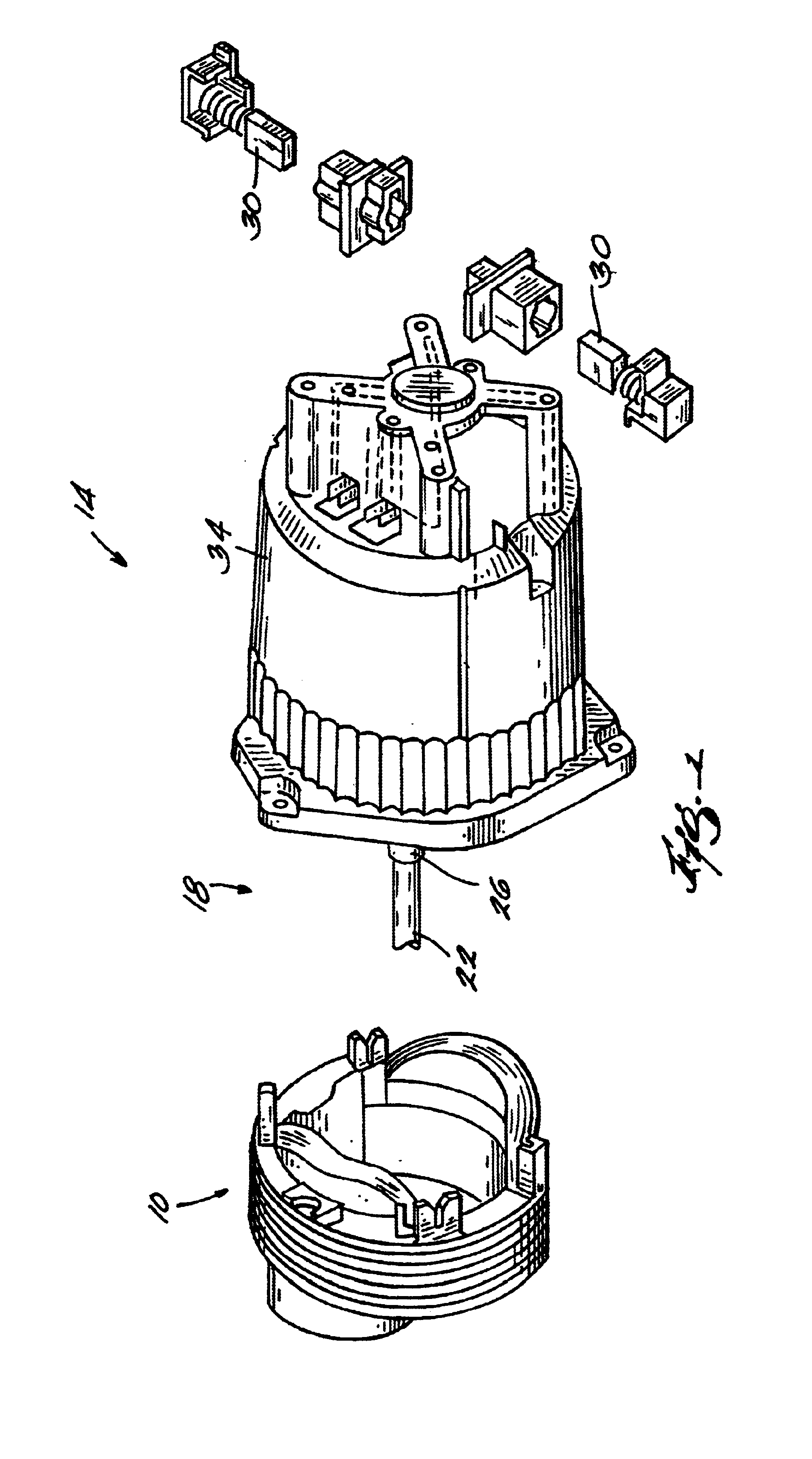
A field assembly 10 embodying the invention and for use in a power tool 14 is illustrated in FIG. 1. The field assembly 10 is a part of an electric motor 18 for the power tool 14. The electric motor 18 is connectable to a power source (not shown) to drive a tool element (not shown).

The electric motor 18 also includes a rotatable shaft or arbor 22 (schematically illustrated in FIG. 1) supporting an armature 26. A pair of brushes 30 transfer electricity to the rotating armature 26 to generate an armature field. The components of the motor 18 are supported by a motor housing 34. The components of the motor 18 are electrically connected to each other and are connectable to the power source by an electrical circuit.

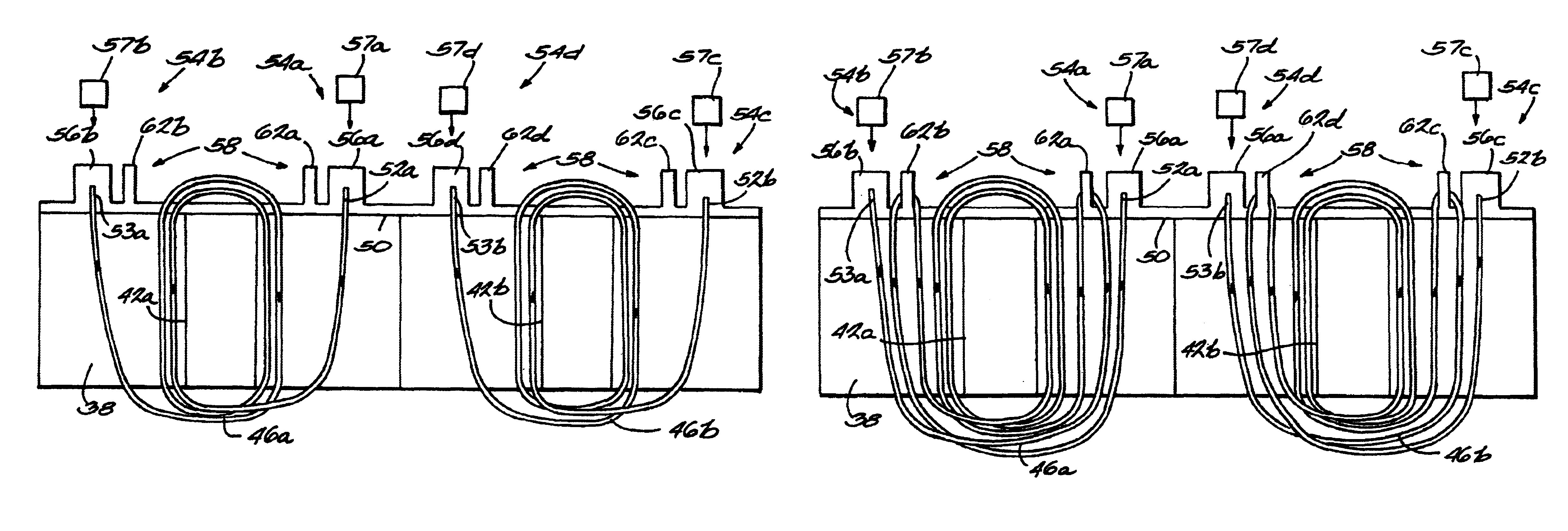
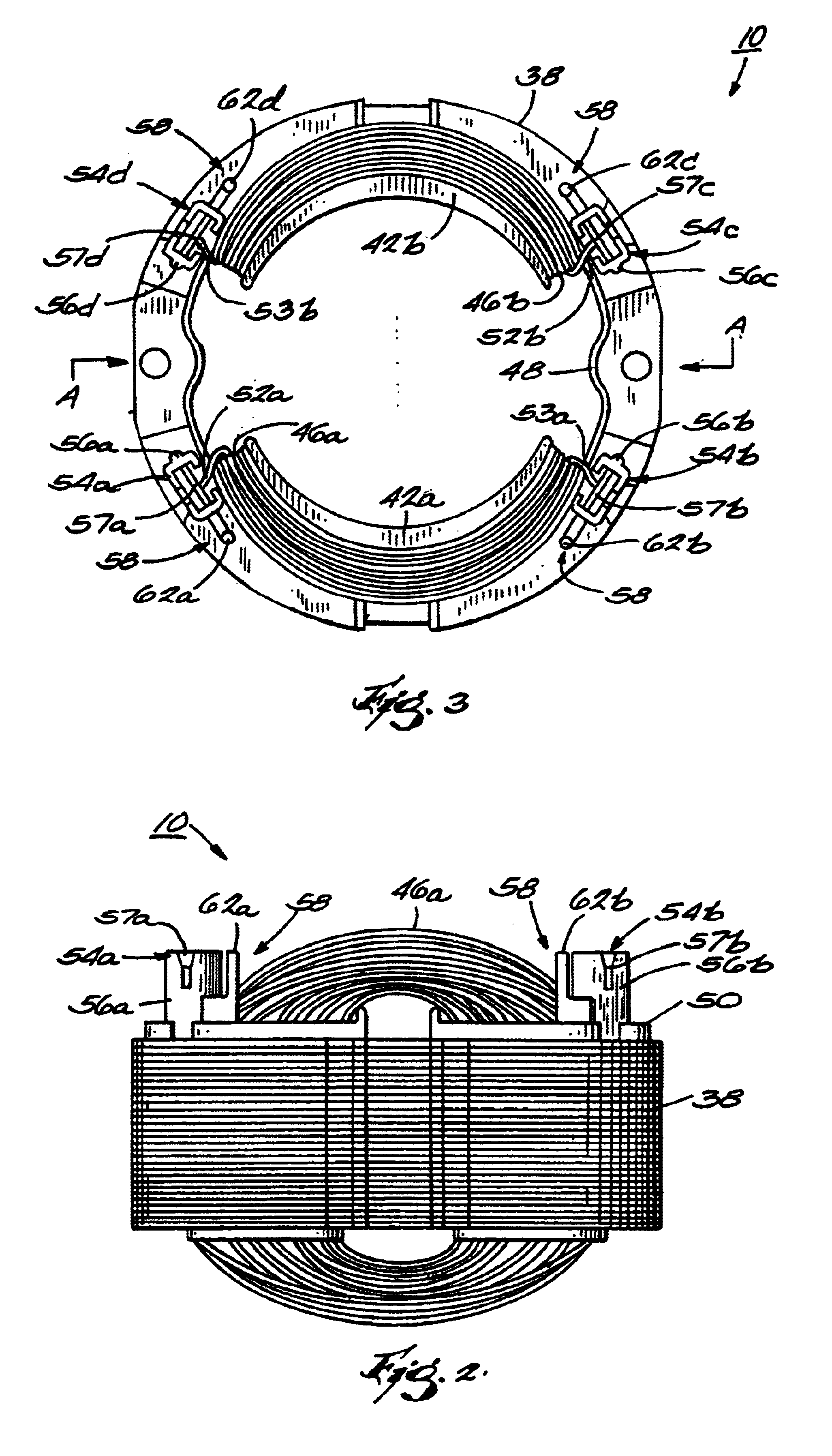
As shown in more detail in FIGS. 2-7, the field assembly 10 includes a field core 38 having a wire or winding support structure 42a-b. One or more coil wires or windings 46a-b are wound on the core 38, as described below in more detail. Insulating material, such as insulation ...


PUM


Abstract

The present invention provides a field assembly for an electric motor and methods for assembling the field assembly. The field assembly includes a winding support and wire redirection structure. The field assembly may be used to manufacture motor assemblies having different polarities (both standard wound and reverse wound) for use with common motor housings, brushes, and wiring.

Description

FIELD OF THE INVENTIONThe invention relates to electric motors and, more particularly, to methods for assembling a field assembly of an electric motor.BACKGROUND OF THE INVENTIONAlternating current (a.c.) universal motors are commonly used in electrical power tools, such as, for example, circular saws, reciprocating saws and drills, and other types of equipment. Generally, these motors are a high-power, light-weight drive source for electric tools.Typically, a universal motor includes a field or stator assembly and a rotatable arbor or shaft having an armature mounted thereon. Current flowing through a run coil of the stator assembly creates a magnetic field that interacts with the armature to rotatably drive the arbor in a direction of rotation. A tool element, such as a saw blade or drill bit, is coupled to the arbor and driven by the motor.A typical field assembly includes an insulated field core having a winding support and a wire or winding wound on the core and the winding sup...

Claims


Application Information

Patent Timeline
IPC IPC(8): H02K3/52H02K7/10H02K7/106H02K3/46H02K15/095H02K15/08H02K15/00
CPCH02K3/522H02K7/106H02K15/0075H02K15/0056H02K2203/06H02K15/095H02K15/0068
Inventor HESSENBERGER, JEFFREY C.CUMMINGS, DAVID H.
Owner MILWAUKEE ELECTRIC TOOL CORP
Why Eureka
Try Eureka