Three-dimensional structure estimation apparatus

Inactive Publication Date: 2005-01-25
NEC CORP
View PDF16 Cites 57 Cited by
  • Summary
  • Abstract
  • Description
  • Claims
  • Application Information

AI Technical Summary

Benefits of technology

It is an object of the present invention to provide a three-dimensional structure estimation apparatus by which a wide visual fiel

Problems solved by technology

Meanwhile, hardware constructions used for stereo methods do not have many variations.
Further, since the directions of the lines of sight or the positions of the cameras are not much different from each other, from the point of view that an image imaged by a single camera is processed, the difference between the images is comparatively small and information included in the images is very redundant.
From this fact, since an additionally provided camera provides only information to be used by a stereo method, it can be considered that much wasteful information is provided by the camera.
Of the various conventional three-dimensional structure estimation apparatus described above, the three-dimensional structure estimation apparatus shown in FIG. 6 has a problem in that, where

Method used


Image

  • Three-dimensional structure estimation apparatus
  • Three-dimensional structure estimation apparatus
  • Three-dimensional structure estimation apparatus

Examples


Embodiment Construction

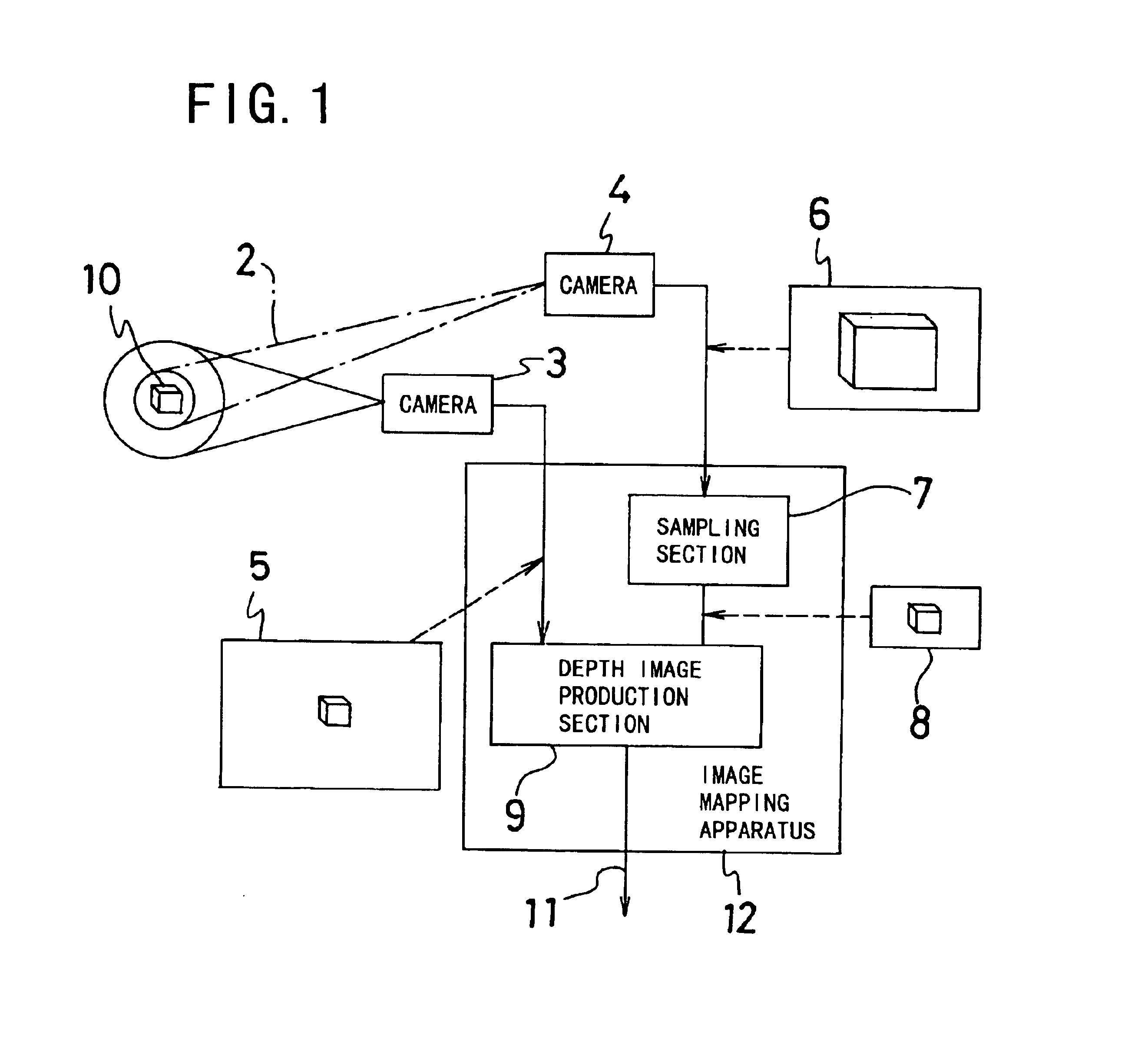
Referring first to FIG. 1, there is shown in block diagram a three-dimensional structure estimation apparatus to which the present invention is applied. The three-dimensional structure estimation apparatus shown includes a wide visual field camera 3 having a wide visual field cone 1 of a wide visual field and a narrow visual field camera 4 having a narrow visual field cone 2 of a narrow visual field. The wide visual field camera 3 and the narrow visual field camera 4 are set so that the visual fields thereof catch a same imaging target 10. The wide visual field camera 3 catches and images the imaging target 10, which makes a target of estimation of a three-dimensional structure, in the wide visual field cone 1 thereof and outputs the imaged imaging target 10 as a wide visual field image 5. Similarly, the narrow visual field camera 4 catches and images the same imaging target 10 in the narrow visual field cone 2 thereof and outputs the imaged imaging target 10 as a narrow visual fiel...


PUM


Abstract

A three-dimensional structure estimation apparatus by which an image of a wide visual field and another image which has a high resolution at part of the visual field are provided and a high resolution three-dimensional structure of an object in the visual field can be estimated is disclosed. A wide visual field image and a narrow visual field image outputted from cameras which have a wide visual field cone and a narrow visual field cone of different visual fields and produce images of different resolutions are converted into images whose pixel units are equal in magnitude by a conversion section. The conversion section includes a sampling section which samples pixels of the narrow visual field image to produce a coincident pixel unit image which has a pixel unit coincident with that of the wide visual field image, and a depth image production section which receives and compares the wide visual field image and the coincident pixel unit image with each other to produce a depth image. Preferably, the sampling section produces a plurality of images of coincident pixels by successively displacing sampling positions little by little so that the depth distance can be estimated with a higher degree of accuracy.

Description

BACKGROUND OF THE INVENTION1. Field of the InventionThis invention relates to a three-dimensional structure estimation apparatus which measures a depth distance of an object on an image and outputs a depth image in application fields in which a depth distance to an object on a image is estimated in the field of computer vision including such fields of supervision of an object, automatic operation and robot automation.2. Description of the Related ArtIn the field of computer vision, a stereo method is utilized popularly as a method of obtaining three-dimensional information from two-dimensional information. The stereo method is a useful technique for obtaining three-dimensional information from paired two-dimensional images. One of such techniques is disclosed, for example, in M. Okutomi and T. Kanade, “A multiple-baseline stereo”, IEEE Transactions on Pattern Analysis and Machine Intelligence, Vol. 15, No. 4, April, 1993, pp.353-363 (reference document 1). The technique of the refer...

Claims


Application Information

Patent Timeline
IPC IPC(8): G01S11/00G01S11/12G03B35/20G06T1/00G09G5/36H04N13/02
CPCH04N13/025G01S11/12H04N13/25
Inventor HOUSE, GREGORY
Owner NEC CORP
Why Eureka
Try Eureka