Liquid crystal display having reflector outside liquid crystal cell

a liquid crystal display and reflector technology, applied in the field of liquid crystal displays, can solve the problems of low overall reflectance of the reflective liquid crystal display b>50/b>, insufficient brightness of the display, and the inability to meet the needs of a reflector that reflects incident light over a greater range of reflection angles, etc., and achieves the effect of bright display and practicality

Inactive Publication Date: 2005-01-25
ONANOVICH GROUP
View PDF2 Cites 74 Cited by
  • Summary
  • Abstract
  • Description
  • Claims
  • Application Information

AI Technical Summary

Benefits of technology

With this structure, external light entering the reflector mainly from above can be reflected in the direction close to the normal direction relative to the substrate surface instead of downward direction when viewed from an observer. Thus, the reflective liquid c

Problems solved by technology

However, in the conventional reflective liquid crystal display 50, because the irregular surface of the reflector 70 subjected to sand-blasting has a poor reflection efficiency, the overall reflectance of the reflective liquid crystal display 50 is low.
In other words, the conventional reflective liquid crystal display 50 fails to meet the needs for a reflector that reflects incident light over a greater range of reflection angles.
The viewing angle of the reflective liquid crystal display 50 including th

Method used


Image

  • Liquid crystal display having reflector outside liquid crystal cell
  • Liquid crystal display having reflector outside liquid crystal cell
  • Liquid crystal display having reflector outside liquid crystal cell

Examples


first embodiment

A first embodiment of the present invention will now be described in detail.

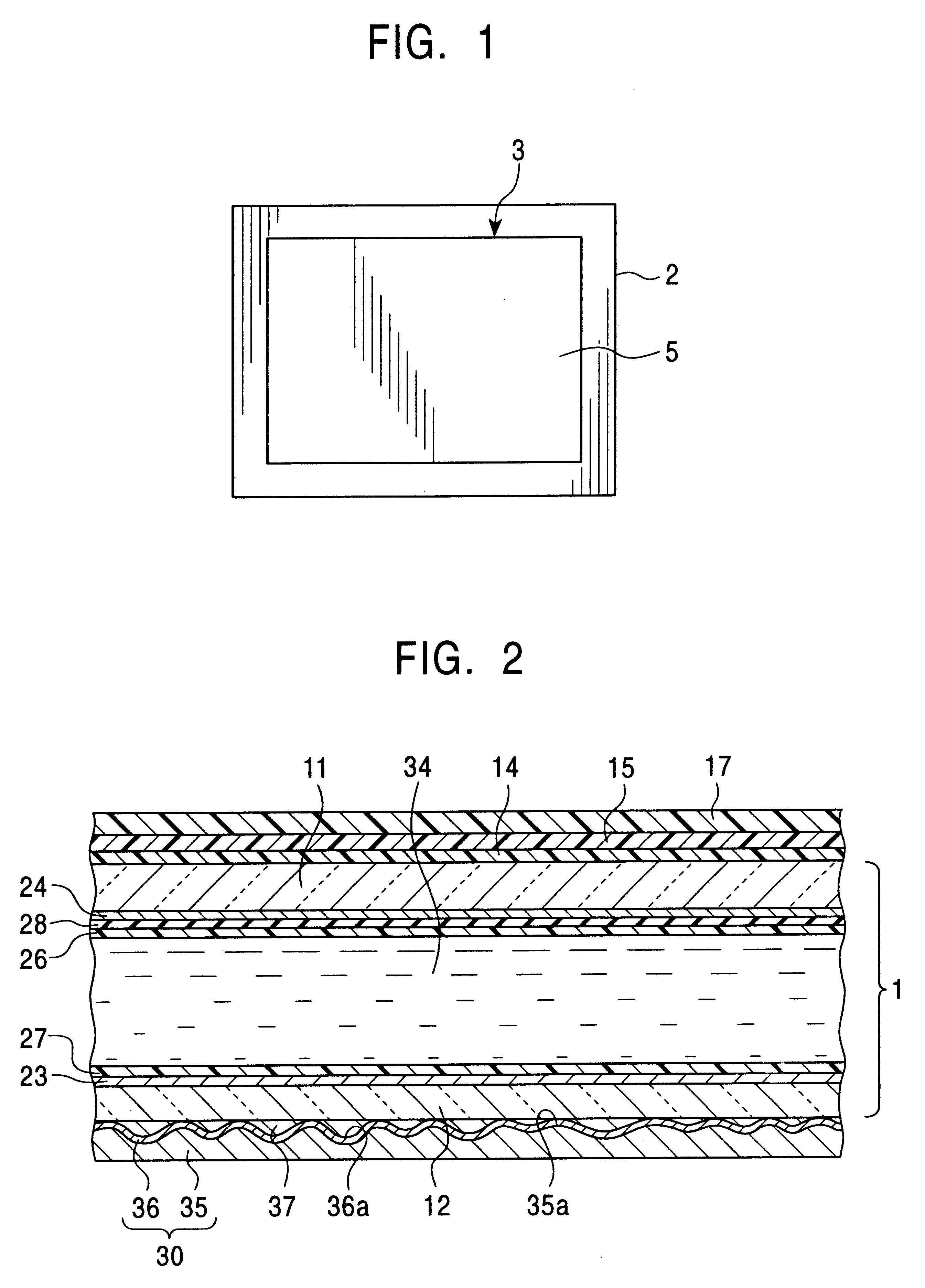
FIG. 1 is a front view of a display unit of a portable information terminal incorporating a liquid crystal display according to a first embodiment of the present invention. The liquid crystal display of this embodiment is a super twisted nematic (STN) reflective liquid crystal display.

The display unit of the portable information terminal of this embodiment has a frame 2 and a reflective liquid crystal display 3 of the present invention. The reflective liquid crystal display 3 is inside the frame 2. The reflective liquid crystal display 3 of this embodiment is of a type that is laid horizontally when used.

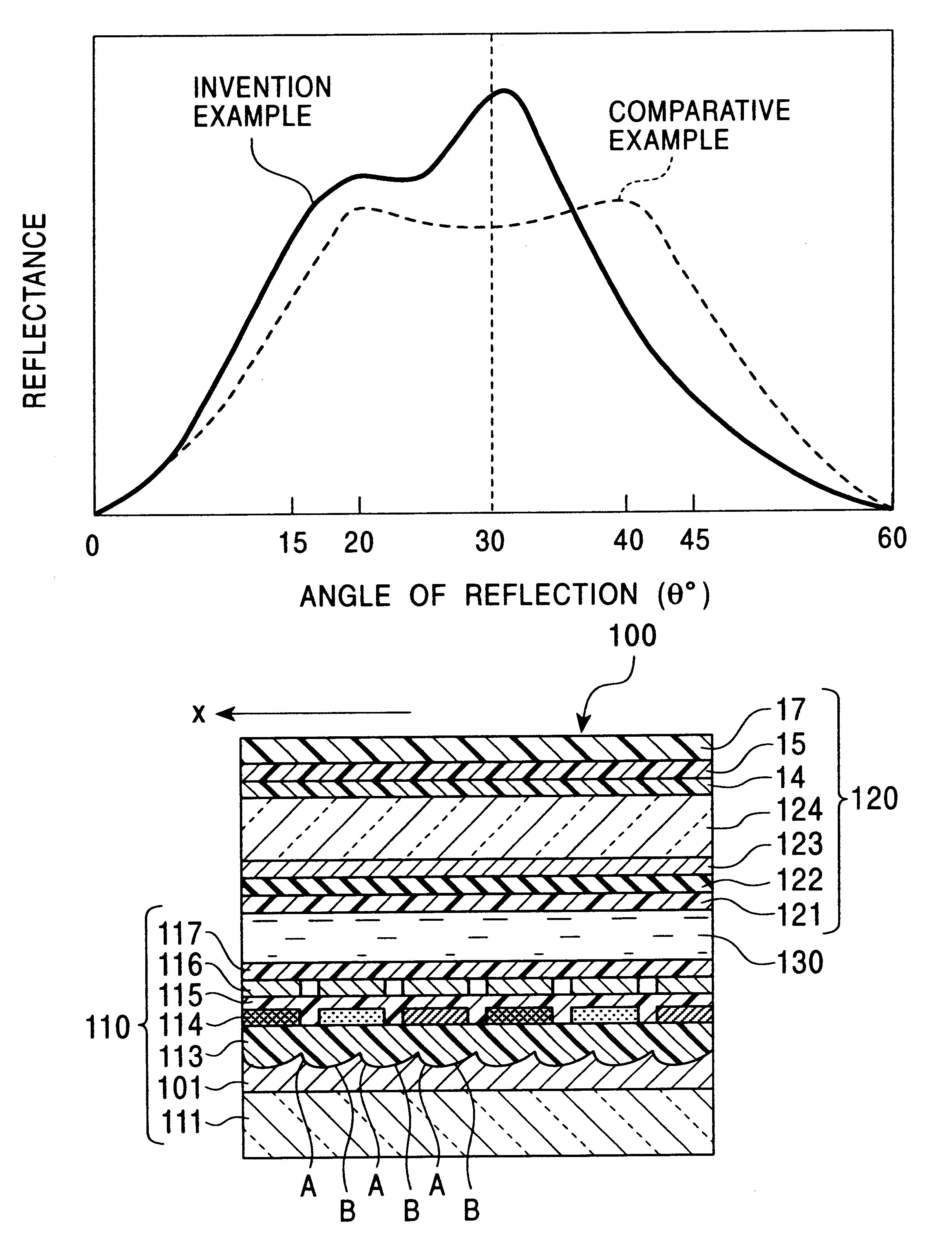
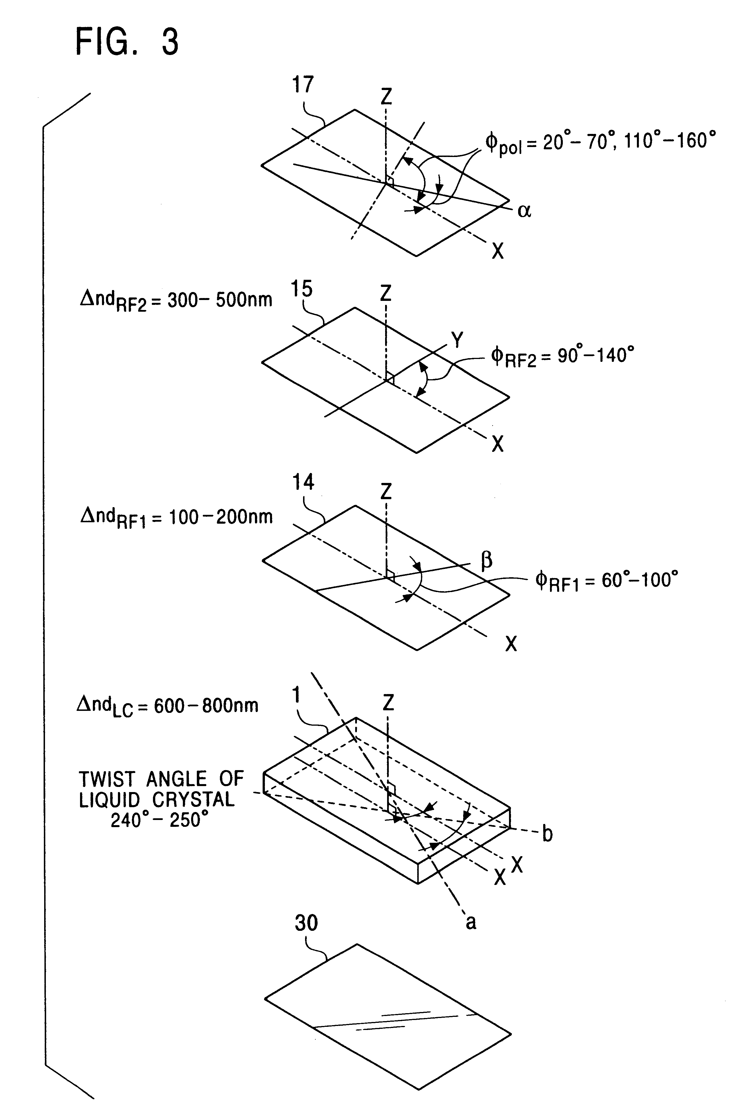
As shown in FIG. 2, the reflective liquid crystal display 3 of this embodiment includes a liquid crystal cell 1, a first retarder 14 disposed on the outer surface of an upper glass substrate 11 of the liquid crystal cell 1, a second retarder 15 disposed on the first retarder 14, and a polarizer 17 disposed o...

second embodiment

FIG. 11 is a partial perspective view of a reflector 101 used in the reflective liquid crystal display 3 according to a second embodiment of the present invention. As shown in FIG. 11, the reflector 101 of this embodiment comprises a base plate 102 composed of, for example, aluminum, surfaces S, i.e., reference surfaces, and a plurality of concavities 103a, 103b, 103c, etc., hereinafter generally referred to as the “concavities 103”. The concavities 103 reflect light and are arranged at random adjacent with one another.

The shape of the inner surface of each concavity 103 is shown in detail in FIGS. 12 to 14. FIG. 12 is a perspective view of the concavity 103, FIG. 13 is a cross-sectional view of the concavity 103 taken through a vertical cross-section X, and FIG. 14 is a cross-sectional view of the concavity 103 taken at a vertical-cross section Y orthogonal to the vertical cross-section X.

As shown in FIG. 13, the shape of the inner surface of the concavity 103 through the vertical ...

examples

The present invention is described in further detail below using Examples and Comparative Examples. These examples do not limit the scope of the present invention.


PUM


Abstract

A liquid crystal display includes a liquid crystal cell including a first transparent substrate and a second substrate, and a reflector attached to the outer surface of the first transparent substrate with a bonding layer therebetween. A first retarder is disposed on the outer surface of the second transparent substrate, a second retarder is disposed on the first retarder, and a polarizer is disposed on the second retarder. The reflector includes a resin substrate having an irregular surface and a metal reflection layer also having an irregular surface that corresponds to the irregular surface of the reflector. The reflector is attached to the liquid cell so that the metal reflector layer faces the first transparent substrate.

Description

BACKGROUND OF THE INVENTION1. Field of the InventionThe present invention relates to a liquid crystal display having a reflector disposed outside a liquid crystal cell. In particular, the present invention relates to a liquid crystal display that achieves a wide viewing angle, a high bright display, and a high contrast without having to provide a retarder between the liquid crystal panel and the reflector outside the liquid crystal panel.2. Description of the Related ArtGenerally, liquid crystal displays can be classified into transflective liquid crystal displays provided with backlights, transmissive liquid crystal displays, and reflective liquid crystal displays depending on the display mode used. Reflective liquid crystal displays do not use backlights and use only external light, such as sunlight and illuminating light. Reflective liquid crystal displays are frequently used in thin, lightweight, portable information terminals that require low power consumption, for example. Ref...

Claims


Application Information

Patent Timeline
IPC IPC(8): G02F1/1335G02F1/13G02B5/02G02B5/08G02F1/13363G09F9/00G09F9/30
CPCG02F1/133553G02F1/13363G02F2413/08G02F2413/02G02F2202/40
Inventor TANADA, TETSUSHIOHIZUMI, MITSUOKANO, MITSURU
Owner ONANOVICH GROUP
Why Eureka
Try Eureka