
Camera system, camera and lens apparatus

Active Publication Date: 2005-01-25
CANON KK
View PDF2 Cites 0 Cited by
  • Summary
  • Abstract
  • Description
  • Claims
  • Application Information

AI Technical Summary

Benefits of technology

It is an object of the present invention to provide a camera system, camera and lens apparatus capable of controlling the driving of a focus lens in an AF function which carries out overlap control to an in-focus position with a high degree of accuracy.
In order to attain the above described object, one aspect of the camera system of the present invention includes a camera system comprising a lens apparatus with an image-taking optical system including a focus lens unit and a camera on which the lens apparatus is mountable. The camera system comprises a focus detection unit which detects a focusing state of the image-taking optical system, a driving unit which drives the focus lens unit, and a controller which controls the driving speed of the focus lens unit through the driving unit and controls the focus detection unit to perform a focus detection operation at least once while the focus lens unit is moved. The controller sets the driving speed of the focus lens unit at the time of at least a final focus detection operation by the focus detection unit while the focus lens is moved toward an in-focus position, to a speed decelerated from the driving speed before the final focus detection operation.
One aspect of the camera of the present invention on which a lens apparatus is mountable, the lens apparatus comprising an image-taking optical system which includes a focus lens unit. The camera comprises a communication unit which communicates with the lens apparatus, a focus detection unit which detects a focusing state of the image-taking optical system, a driving unit which drives the focus lens unit, and a controller which controls the driving speed of the focus lens unit through the driving unit and through communications with the lens apparatus through the communication unit and controls the focus detection unit to perform a focus detection operation at least once while the focus lens unit is moved. The controller sets the driving speed of the focus lens unit at the time of at least the final focus detection operation by the focus detection unit while the focus lens unit is moved toward an in-focus position, to a speed decelerated from the driving speed before the final focus detection operation.

Problems solved by technology

However, with the trend toward implementation of an image-pickup element with a multitude of pixels and a smaller in size in a digital camera system in recent years, there is a growing demand for an AF function with a higher degree of accuracy and the above described AF has problems as shown below.
According to the AF system disclosed in the above described Publication, the focus detection operation during the driving of the focus lens is carried out at constant intervals, and therefore the position of the focus lens when the focus detection operation is carried out immediately before the driving is completed changes according to the amount of driving of the focus lens based on the initial focus detection operation, resulting in a problem that the accuracy of focus detection and accuracy of calculations of the amount of driving of the lens are not stable.
Furthermore, in a recent camera system capable of faster driving of the focus lens in order to reduce the focusing time, there are problems such as deterioration of focus detection accuracy due to an image flow on a focus detection sensor caused by the driving of the focus lens and deterioration of accuracy of focus detection and accuracy of calculations of the mount of driving where the focus detection operation immediately before the driving is completed is considerably far from the in-focus position.

Method used


Image

  • Camera system, camera and lens apparatus
  • Camera system, camera and lens apparatus
  • Camera system, camera and lens apparatus

Examples


embodiment 1

(Embodiment 1)

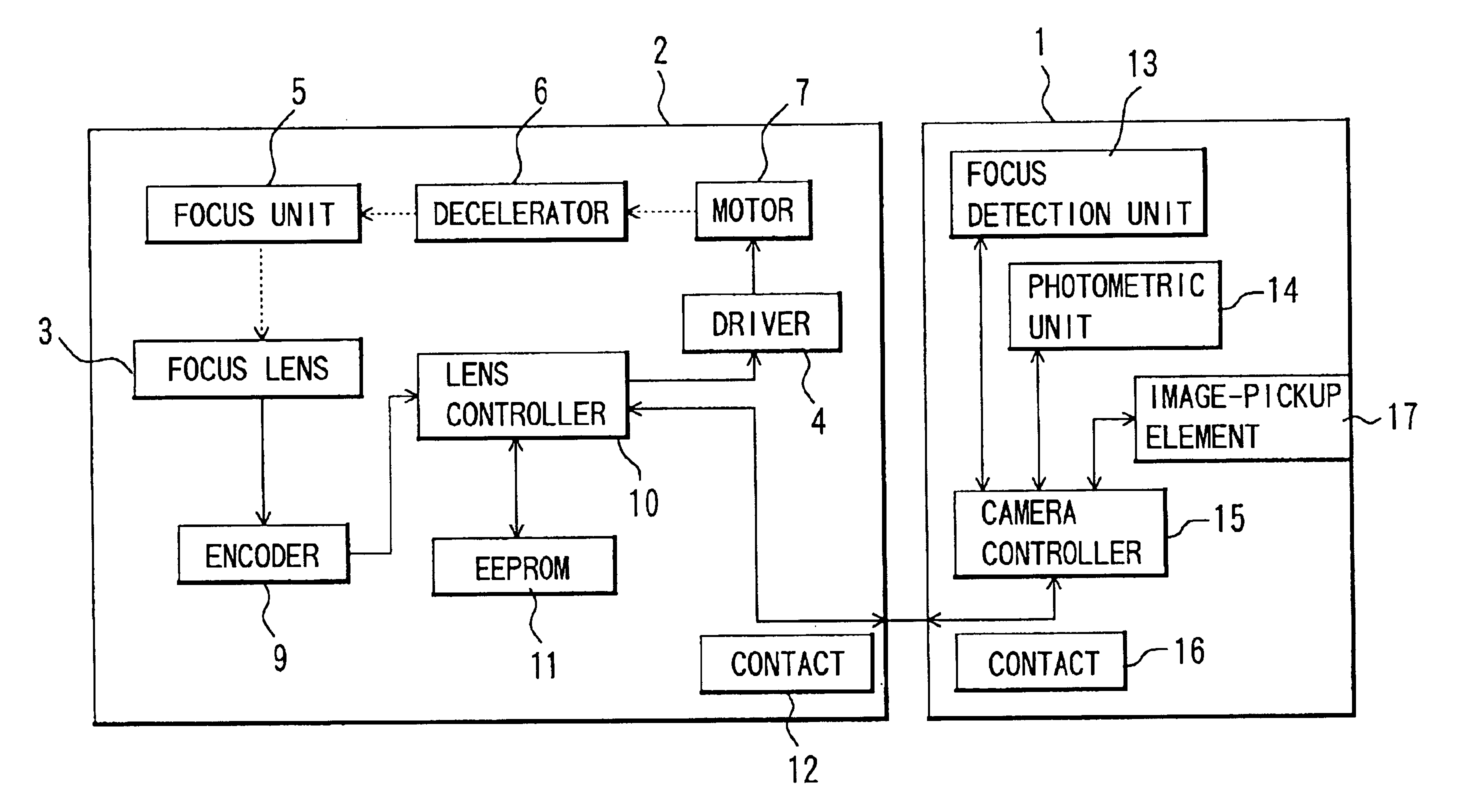
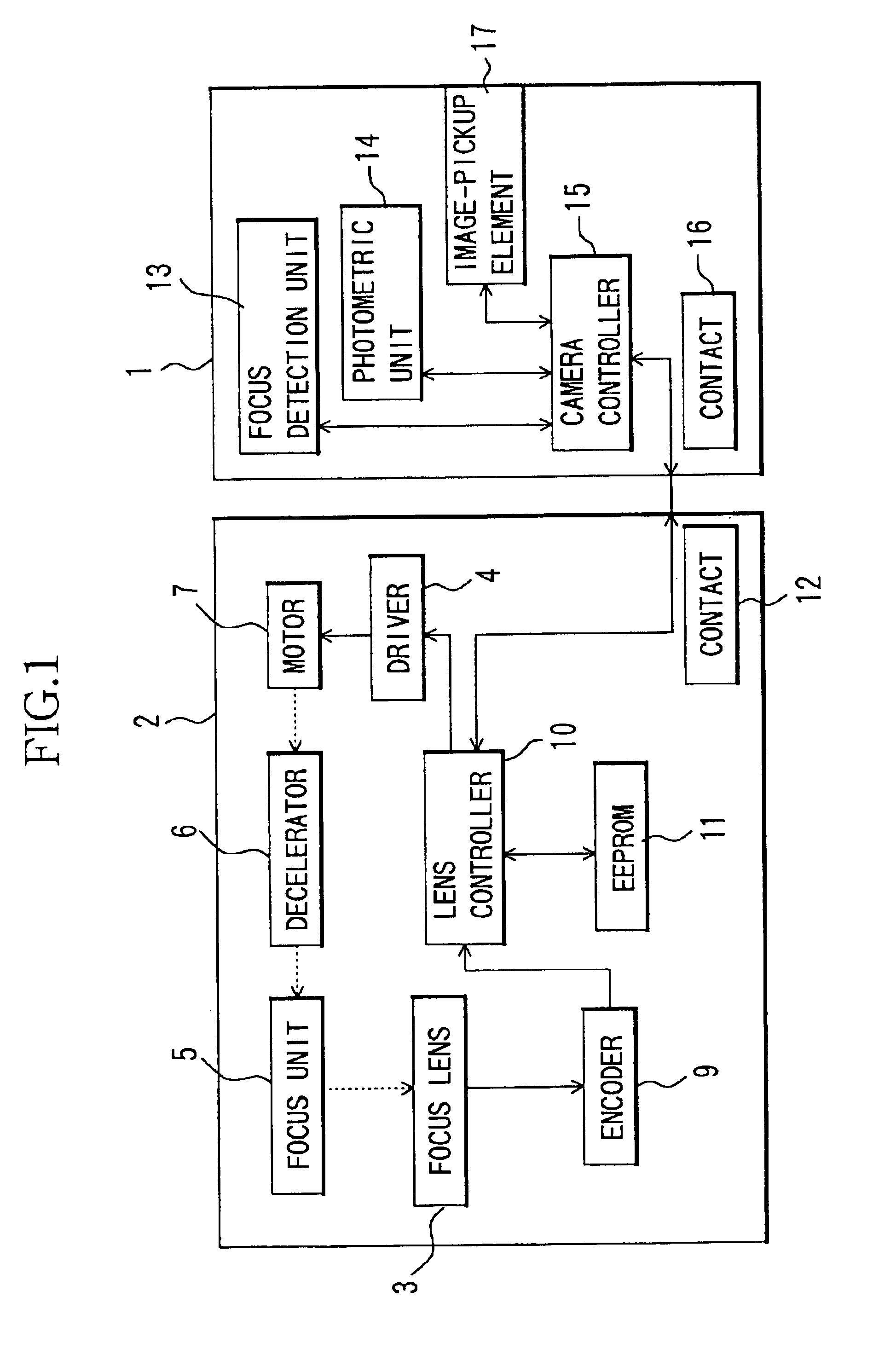
FIG. 1 shows a structure of a lens interchangeable type camera system according to Embodiment 1. In FIG. 1, reference numeral 1 denotes a camera (digital still camera), 2 denotes an image-taking lens (lens apparatus) which is attached to the camera 1. In FIG. 1, dotted lines express mechanical connections and solid lines express electrical connections.

First, the structure of the image-taking lens 2 will be explained. Reference numeral 7 denotes a motor which is the power source to generate a driving force for the focus lens 3 which moves for focusing, 6 denotes a decelerator which decelerates the output of the motor 7 and increases torque, 5 denotes a focusing unit including a cam cylinder, etc., which converts the output from the decelerator 7 to a driving force in the direction of the optical axis of the focus lens 3.

Reference numeral 10 denotes a lens controller which controls all units in the image-taking lens 2, which consists of a microcomputer. Reference numeral...

embodiment 2

(Embodiment 2)

Above described Embodiment 1 has described the camera system allowing the mounting of the image-taking lens in the camera, but the present invention is also applicable to a lens-integral type camera.

FIG. 6 shows a lens-integral type camera of Embodiment 2 of the present invention. In this camera 1′, the same components as those in Embodiment 1 are assigned the same reference numerals as those in Embodiment 1.

In this case, the functions of the lens controller of Embodiment 1 are included in the camera controller 15 and the camera controller 15 performs overall control including the overlap control explained in Embodiment 1.


PUM


Abstract

A camera system which controls the driving of a focus lens through overlap control with a high degree of accuracy, is disclosed. The camera system comprises a lens apparatus with an image-taking optical system and a camera on which the lens apparatus is mountable. The camera system comprises a focus detection unit detecting a focusing state of the image-taking optical system, a driving unit driving the focus lens unit, and a controller controlling the driving speed of the focus lens unit and controls the focus detection unit to perform a focus detection operation at least once while the focus lens unit is moved. The controller sets the driving speed of the focus lens unit at the time of at least a final focus detection operation while it is moved toward an in-focus position, to a speed decelerated from the driving speed before the final focus detection operation.

Description

BACKGROUND OF THE INVENTION1. Field of the InventionThe present invention relates to a lens apparatus, camera system and camera provided with an autofocusing function.2. Description of the Related ArtThere are many camera systems provided with an autofocusing (AF) function which detects a focusing state of an image-taking optical system using a focus detection sensor and moves a focus lens to an in-focus position using an actuator according to the detected signal. There are also a variety of autofocusing systems.For example, a camera system which performs an AF operation based on a TTL phase difference detection system disclosed in Japanese Patent Publication No. H4 (1992)-10051, repeatedly performs focus detections not only before starting the driving of the focus lens but also during the driving of the focus lens, so-called overlap control, in order to shorten the time required to reach an in-focus state and moves the focus lens to the in-focus position while correcting the amount...

Claims


Application Information

Patent Timeline
IPC IPC(8): G03B13/36G02B7/08G02B7/09G02B7/28H04N5/232H04N101/00
CPCG03B13/36
Inventor KASHIWABA, SEIICHIKAWAI, TORUISHIKAWA, MASANORISATO, SHIGEKI
Owner CANON KK
Features
  • Generate Ideas
  • Intellectual Property
  • Life Sciences
  • Materials
  • Tech Scout
  • Unparalleled Data Quality
  • Higher Quality Content
  • 60% Fewer Hallucinations
Learn More