Injection control for a common rail fuel system

a fuel system and injection control technology, applied in the field of system, can solve the problems of difficult control and difficult task to achieve, and achieve the effect of accurate injection control

Inactive Publication Date: 2005-02-01
DETROIT DIESEL CORP
View PDF9 Cites 35 Cited by
  • Summary
  • Abstract
  • Description
  • Claims
  • Application Information

AI Technical Summary

Benefits of technology

The present invention provides a system and method for controlling multiple fuel injections during a single combustion cycle for a multiple cylinder internal combustion engine having a common rail fuel distribution system with the beginning of injection for the pilot and main injections based on crankshaft position while post inje

Problems solved by technology

However, many factors affect the injection events, such as common rail fuel pressure and injector energizing time, for example, making this a difficult task to accomplish.
While this strategy is acceptable for

Method used


Image

  • Injection control for a common rail fuel system
  • Injection control for a common rail fuel system
  • Injection control for a common rail fuel system

Examples


Embodiment Construction

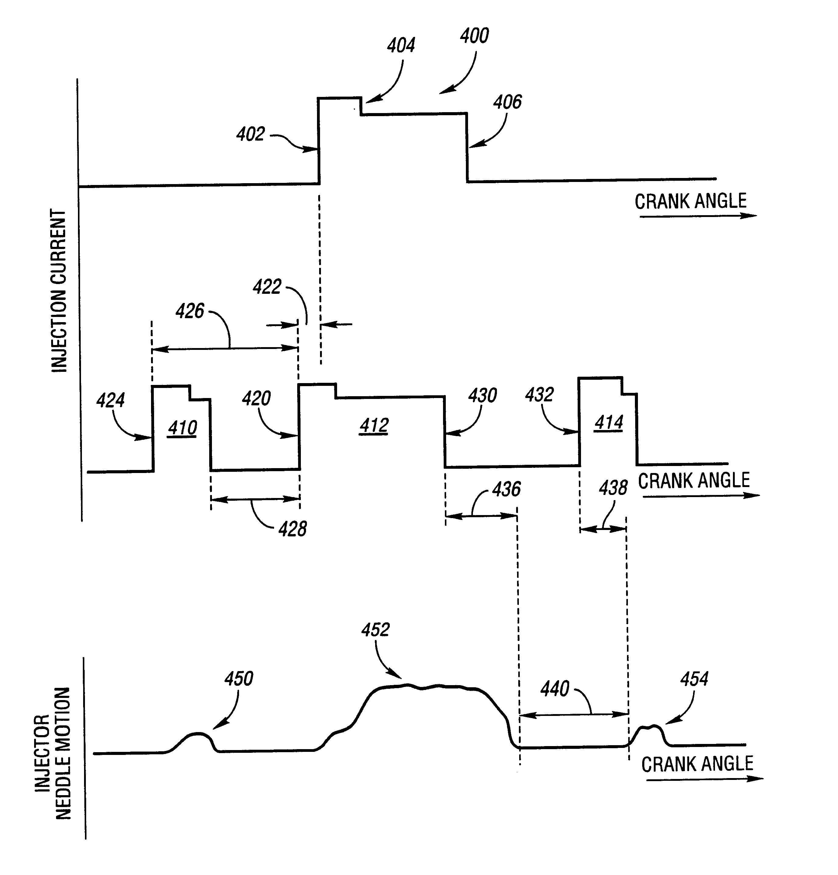
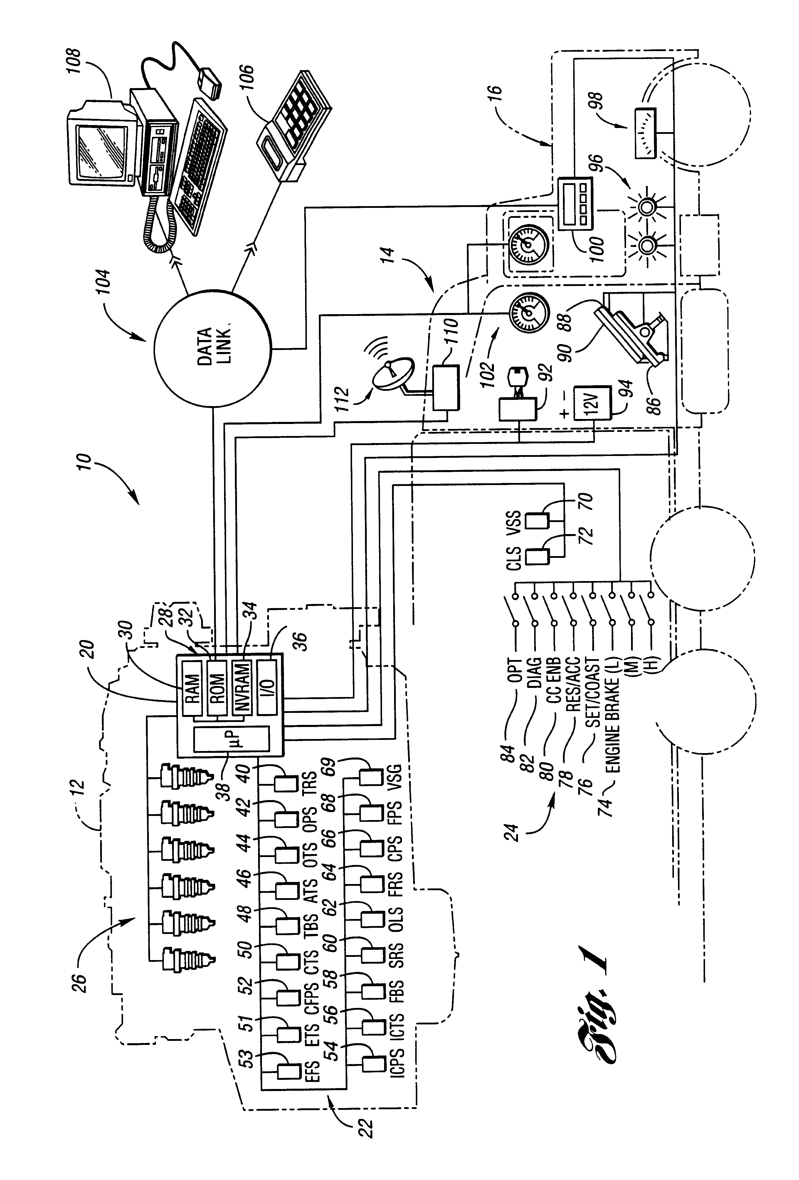
FIG. 1 provides a schematic / block diagram illustrating operation of a system or method for controlling multiple fuel injections for an internal combustion engine having a common rail fuel distribution system according to one embodiment of the present invention. As will be appreciated by those of ordinary skill in the art, the multiple fuel injections include what is typically referred to as a main injection in addition to a pilot injection occurring before the main injection and / or one or more post injections occurring after the main injection. While the main injection is generally a longer duration injection that delivers a fuel quantity greater than the pilot and post injections, the principles of the present invention apply to other applications and operating conditions regardless of the relative durations of the injection events and corresponding quantities of fuel delivered.

Representative system 10 includes a multi-cylinder compression ignition internal combustion engine, such ...


PUM


Abstract

A system and method for controlling multiple fuel injections during a single combustion cycle for a multiple cylinder internal combustion engine having a common rail fuel distribution system determine the beginning of injection for the pilot and main injections based on crankshaft position while post injections are based on the main injection timing and an injector turn off delay determined using actual rail pressure. A rail pressure setpoint is determined based on current engine operating conditions including one or more fluid temperatures and current operating mode to provide more accurate injection control.

Description

BACKGROUND OF THE INVENTION1. Field of the InventionThe present invention relates to a system and method for controlling fuel injection of a common rail fuel system in a multi-cylinder internal combustion engine.2. Background ArtCommon rail fuel systems are used in various types of internal combustion engines, such as diesel engines, for example. An accumulator or rail is used to distribute fuel to injectors or nozzles associated with each cylinder of the engine. An engine control module communicates with various engine components including one or more fuel pumps and fuel injectors to meter the fuel delivered to each cylinder, i.e. control the quantity and timing of the fuel delivery to ultimately control the performance and emissions of the engine.A number of strategies have been developed to control fuel injection in an attempt to improve engine performance and fuel economy while reducing emissions. One such strategy employs multiple fuel injections during a single combustion cycl...

Claims


Application Information

Patent Timeline
IPC IPC(8): F02D41/40F02D41/38F02M45/02F02M45/04F02M45/00
CPCF02D41/3836F02D41/401F02D41/403F02D41/405Y02T10/44F02D2250/31F02M45/02F02M45/04F02D2200/0602Y02T10/40
Inventor WEST, JAMES A.MCCARTHY, JR., JAMES E.
Owner DETROIT DIESEL CORP
Why Eureka
Try Eureka