Umbrella canopy orientating device

Inactive Publication Date: 2005-02-01
MA JOEN SHEN
View PDF7 Cites 15 Cited by
  • Summary
  • Abstract
  • Description
  • Claims
  • Application Information

AI Technical Summary

Benefits of technology

An object of the present invention is to provide a canopy orientating device

Problems solved by technology

Such an orientating mechanism has a complicated structure and thus difficult to operate.
In addition, the complicated structure raises the manufacturing costs of the umbrella.
Again, the structure of th

Method used


Image

  • Umbrella canopy orientating device
  • Umbrella canopy orientating device
  • Umbrella canopy orientating device

Examples


Embodiment Construction

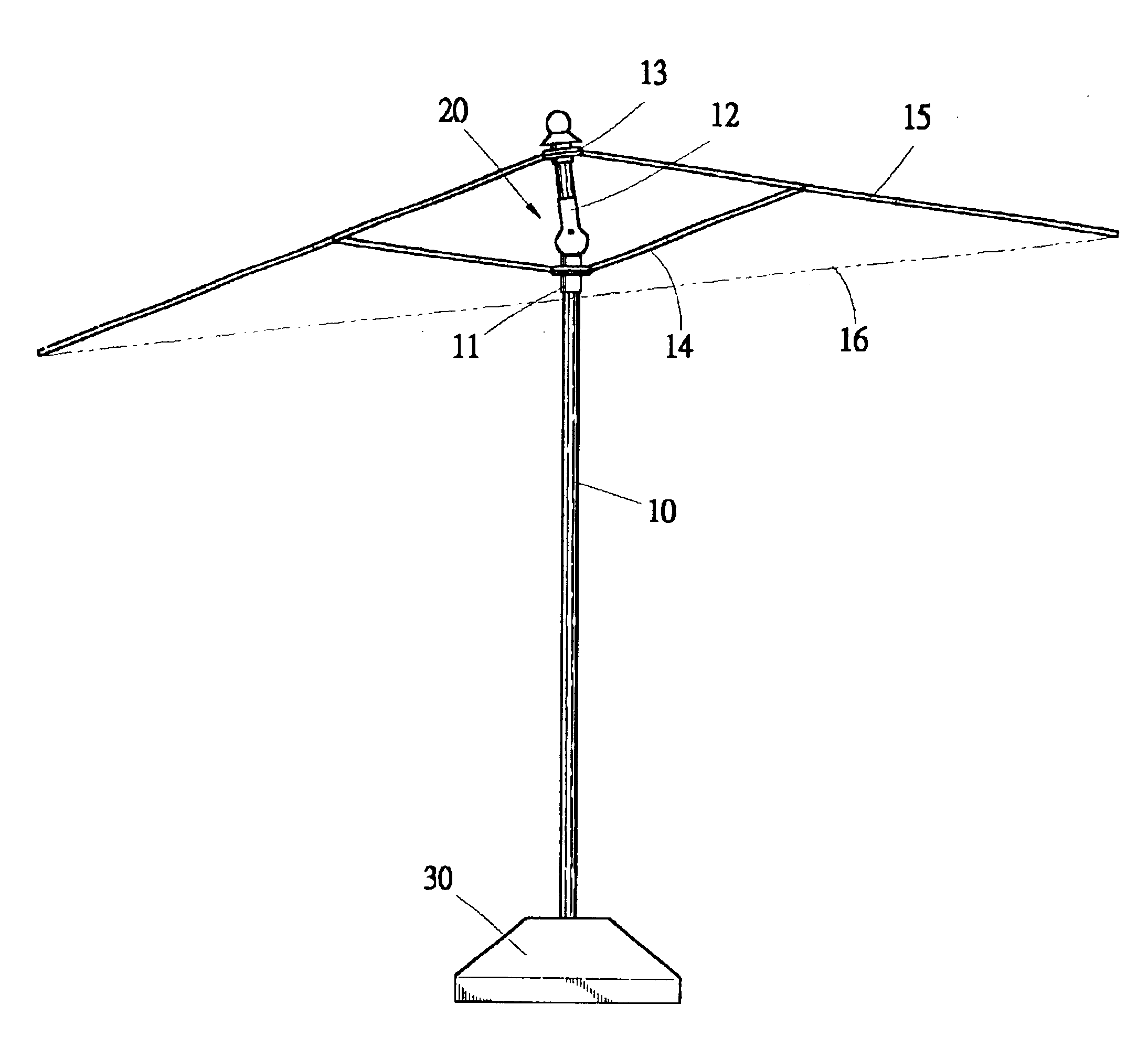
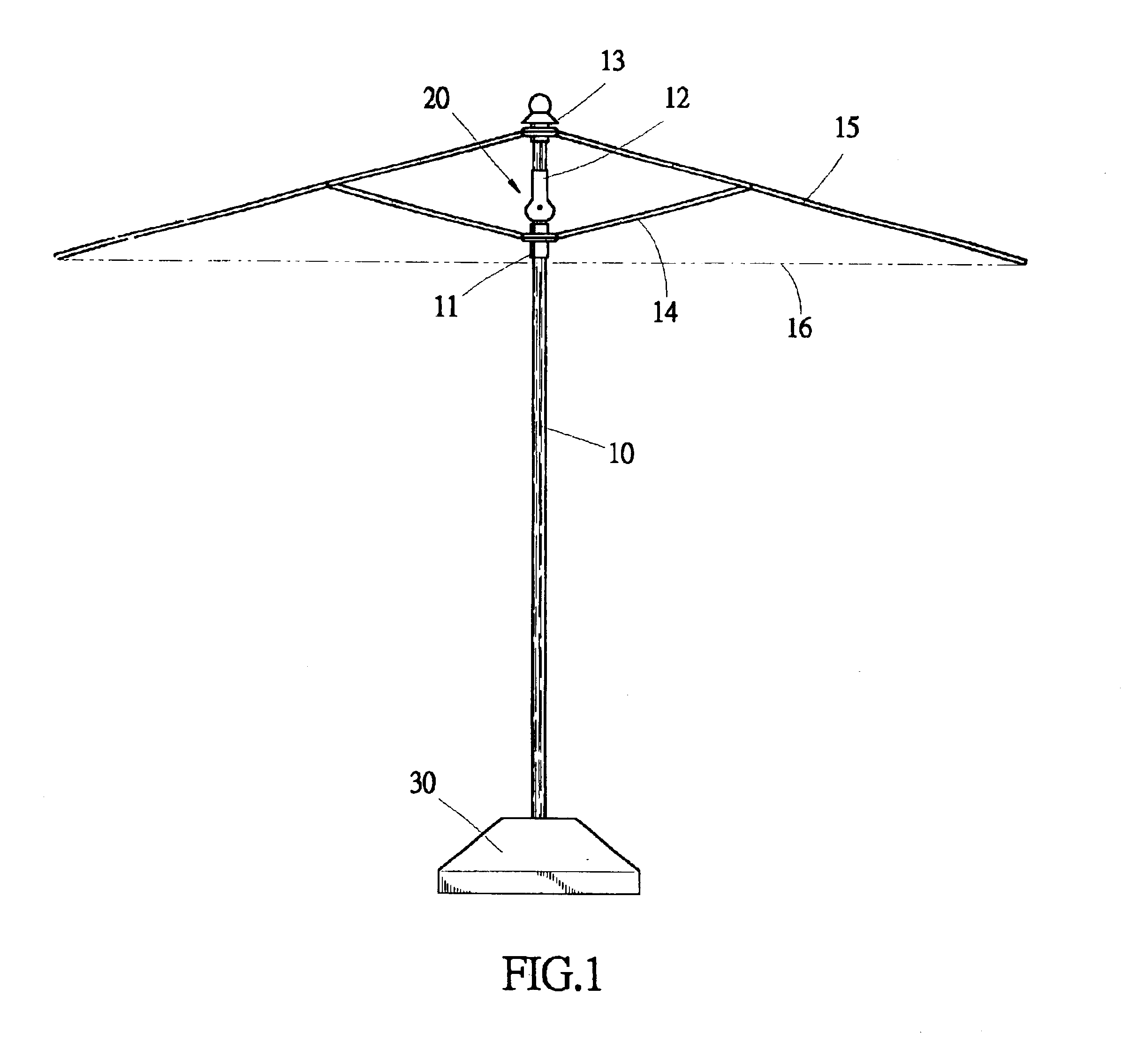
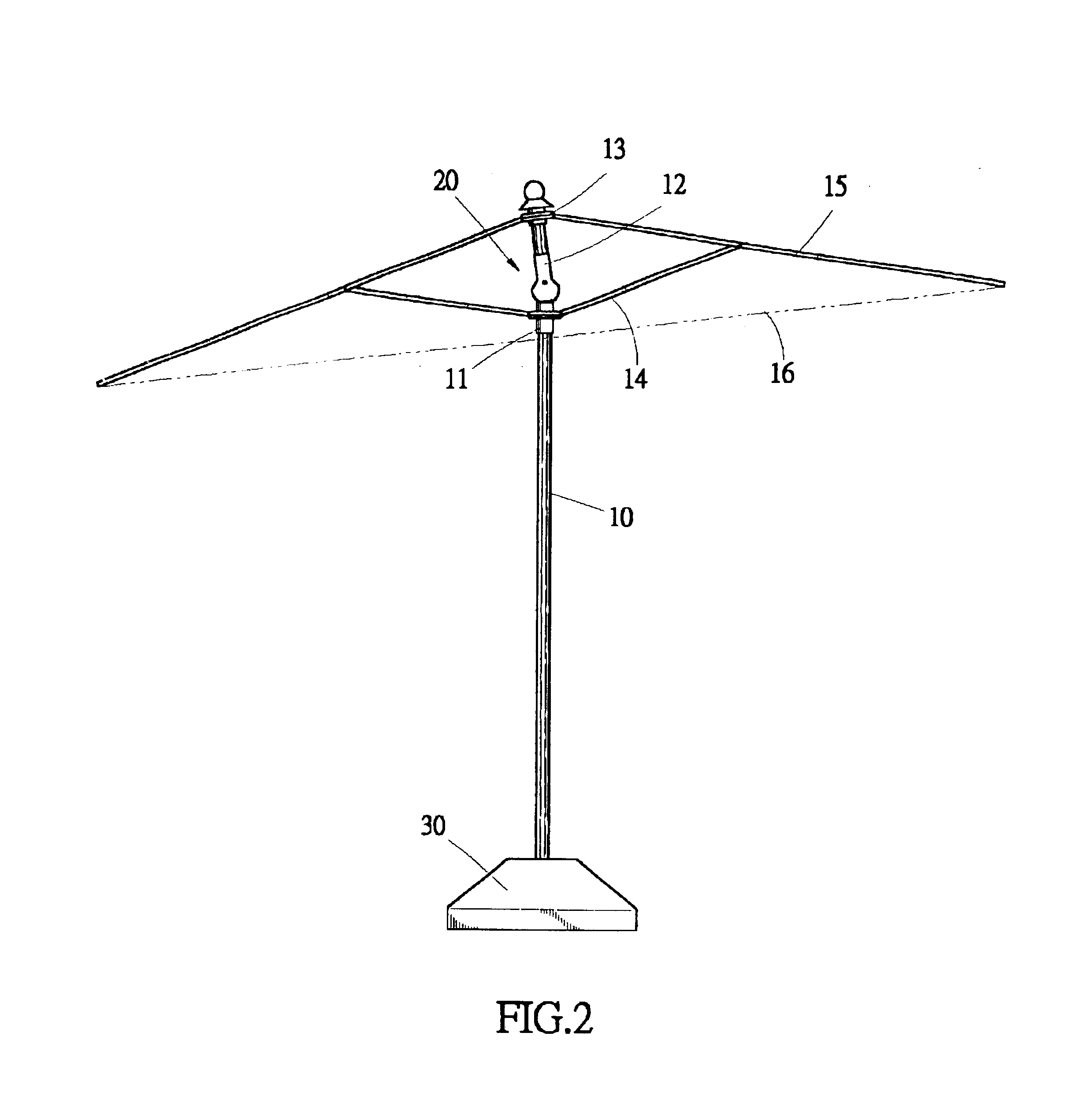
With reference to the drawings and in particular to FIGS. 1, 2 and 3, an umbrella having a canopy orientating device 20 of the present invention is embodied is shown. The canopy orientating device 20 is applied to a large-sized umbrella. The umbrella comprises a central rod arranged on an upright manner. The central rod comprises a lower section 10 and an upper section 12. The lower section 10 has a lower end mounted to a base 30 positioned on a fixed surface. The upper section 12 has an upper end to which a crown 13 is attached. A runner 11 is movably fit over and slidable along the lower section 10 of the central rod. A plurality of ribs 15 is pivotally attached to the crown 13 and radially extends from the crown 13 for supporting a canopy 16. A stretcher 14 has opposite ends respectively pivoted to the runner 11 and each rib 15. Moving the runner 11 toward the crown 13 drives the stretchers 14 to expand the ribs 15, thus opening the umbrella canopy 16, and moving the runner 11 aw...


PUM


Abstract

An umbrella canopy orientating drive is applied to a large-sized umbrella. The umbrella has a central rod comprised of an upper section to which a canopy is attached and a lower section positionable on a fixed surface. The umbrella canopy orientating device includes a diverging portion having a skirt-like opening to receive the lower section of the central rod; a tube portion receiving the lower end of the upper section of the central rod; a pair of pin holes formed on the diverging portion; a pin hole formed through the upper end of the lower section; and a pin inserted through the pin holes of the diverging portion and the pin hole of the lower section to pivot the diverging portion and lower section, whereby the upper section and thus the canopy are allowed to rotate about the pivot pin with respect to the lower section between a neutral position and an inclined position to orientate the canopy in an inclined direction with respect to the lower section.

Description

BACKGROUND OF THE INVENTION1. Field of the InventionThe present invention generally relates to a large-sized umbrella, and in particular to an umbrella having a canopy that is capable to be oriented in inclined directions.2. The Related ArtLarge-sized umbrellas are widely used in a variety of applications, such as beach umbrellas and garden umbrellas, for shading intense sunlight. Thus, some of the large-sized umbrellas are provided with a mechanism for orienting the canopy in order to adapt to the direction of sunlight. Such a mechanism is often mounted on a central rod of the umbrella. The most commonly seen mechanism for orienting the canopy is a pivotal joint formed between upper and lower sections of the central rod that allows for rotation of the upper section on which the canopy is mounted with respect to the lower section that is secured on ground. A latch is arranged between the upper and lower sections to engage holes defined in the central rod in order to selectively fix ...

Claims


Application Information

Patent Timeline
IPC IPC(8): A45B25/18A45B23/00A45B17/00A45B25/00
CPCA45B17/00A45B23/00A45B25/18Y10T403/32951Y10T403/32557Y10T403/32319A45B2023/0012
Inventor MA, JOEN-SHEN
Owner MA JOEN SHEN
Why Eureka
Try Eureka