Fuel pressure damping system and method

a technology of damping system and fuel pressure, which is applied in the direction of instruments, lighting and heating apparatus, machines/engines, etc., can solve the problems of objectionable noise, vibration and harshness, unwanted variation of fuel injector performance, and commercially feasible or physically practicable to introduce a custom-designed damping system

Inactive Publication Date: 2005-02-01
COOPER STANDARD AUTOMATIVE INC
View PDF23 Cites 37 Cited by
  • Summary
  • Abstract
  • Description
  • Claims
  • Application Information

AI Technical Summary

Benefits of technology

The present invention overcomes the disadvantages of conventional compliance damping approaches by including one or more restrictors that work in conjunction with the systems compliance dampers or inherent compliance to achieve the desired damping of pressure fluctuations practically, cost effectively and in a way that does not lower additional harmonic modes into the operating frequency range of the fuel system. The invention introduces specifically sized restrictors in the fuel passage to control the maximum operating system pulse magnitude as well as damping the overall pulsations of the system.
It is an object and advantage that the present invention results in avoiding objectionable pressure fluctuations in a fuel system in a practical, cost effective way.
It is an additional object and advantage that the present invention results in limiting maximum operating system pulse magnitudes without introducing additional harmonic modes into the operating frequency range of the fuel system.

Problems solved by technology

Adding compliance is not always sufficient to relieve all of the objectionable pressure variations in the fuel system however, resulting in unwanted variation of the fuel injector performance as well as objectionable noise, vibration and harshness.
In some systems where adding sufficient compliance is possible it may not be commercially feasible or physically practical to introduce a custom designed compliance damping system.
The additional compliance may make certain members to weak to function properly or require expensive materials to achieve the desired effect.
Additionally, a problem arises when the injector frequency excites one of the various resonant modes of the fuel rail or other system component.
Attempting to resolve these resonant frequency issues simply by adding more compliance can result in other unwanted effects.
Adding more compliance may allow more pulsations to be absorbed, but it will also result in a shift in resonant frequency.
Therefore, adding more compliance can sometimes result in more objectionable resonant frequency modes than before.

Method used


Image

  • Fuel pressure damping system and method
  • Fuel pressure damping system and method
  • Fuel pressure damping system and method

Examples


Embodiment Construction

)

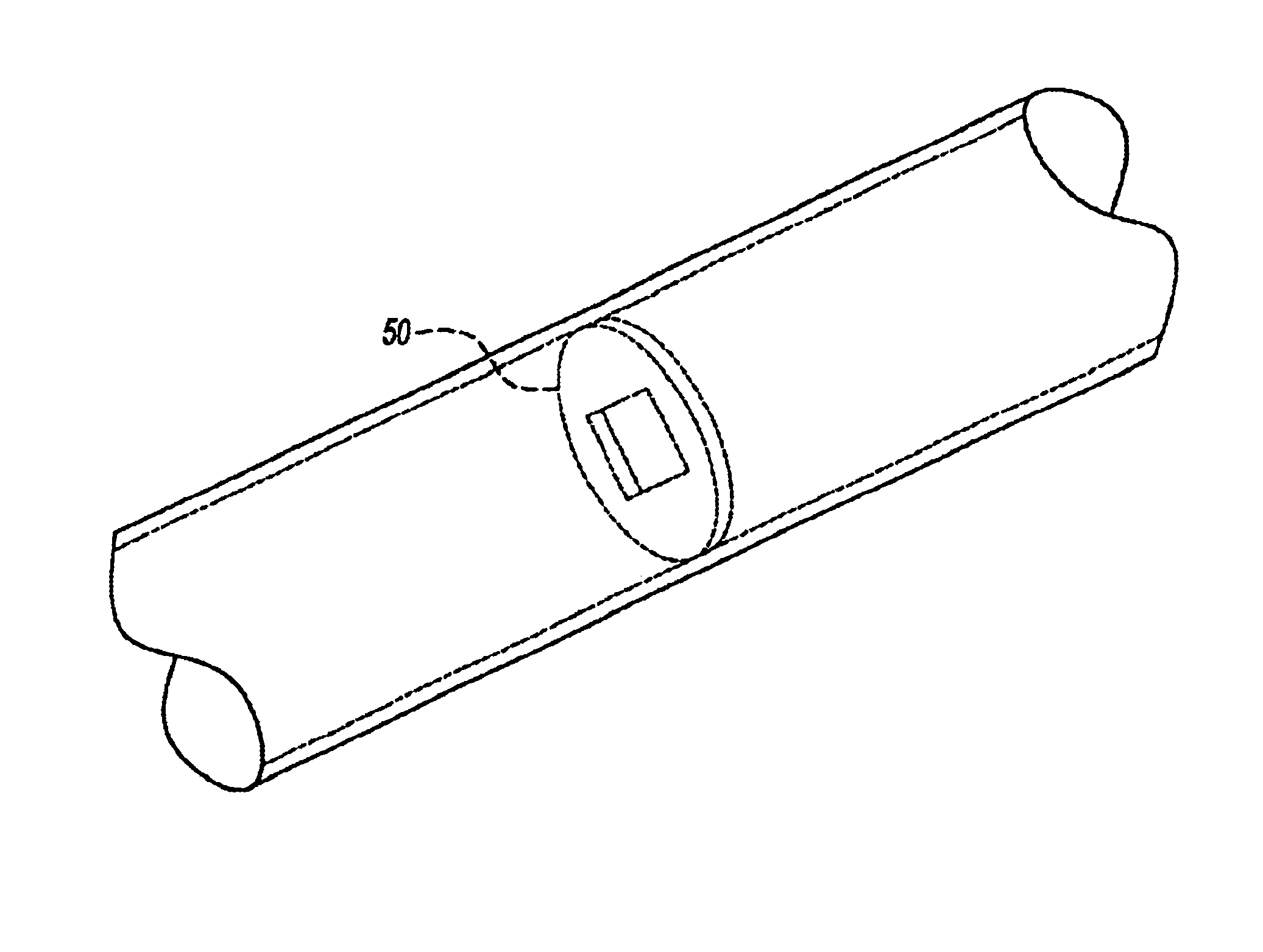
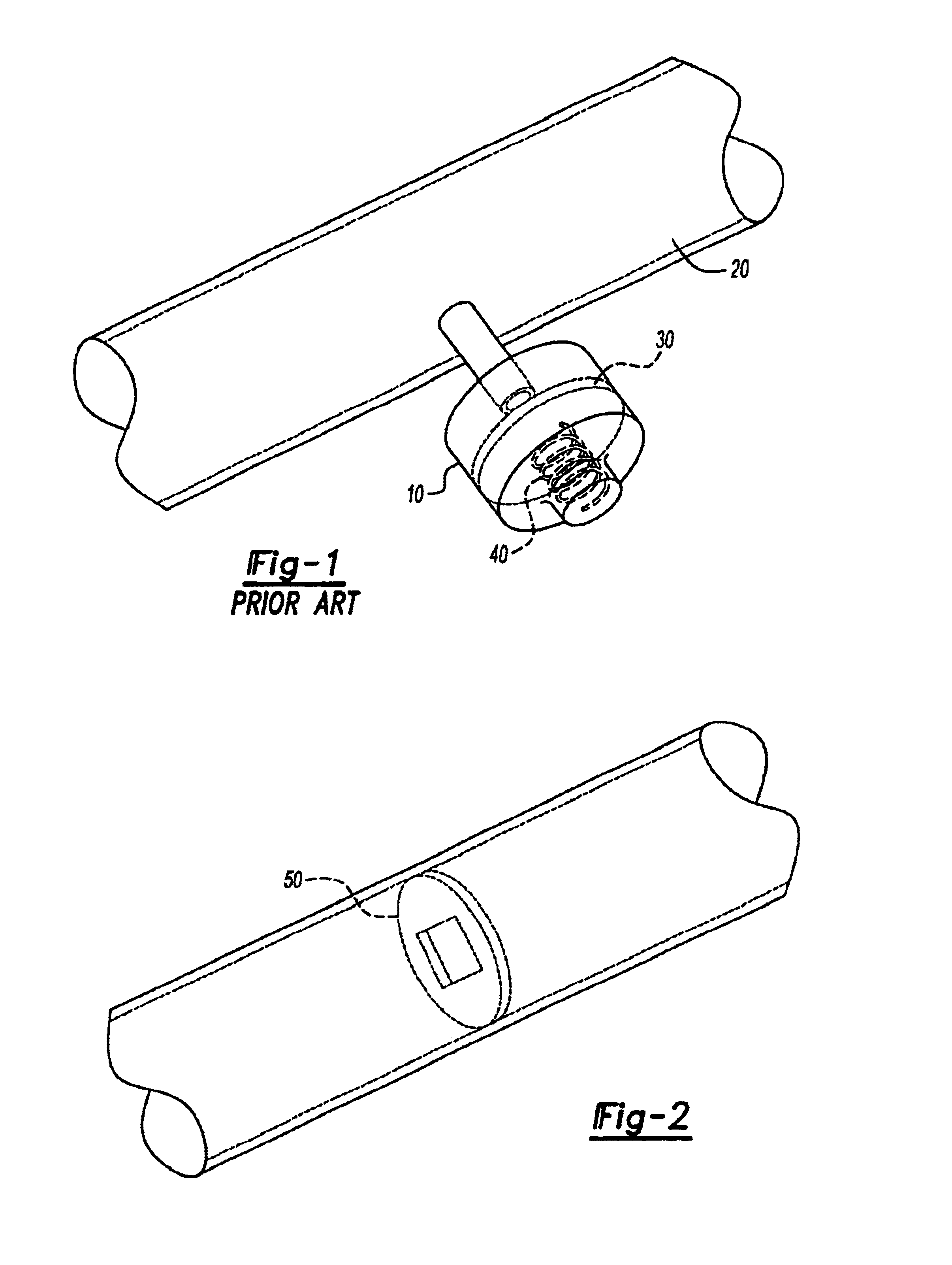
Referring now to the drawings, FIG. 1 illustrates a conventional hydraulic pulse damping system, such as used in a fuel system. Pressure pulsations in many hydraulic systems are a natural results of inputs to and outputs from the system. AS discussed above, these pressure pulsations can add unwanted pressure fluctuations at the fuel injector noise, vibration and / or harshness to the operation of the system throughout the operating frequency range of the system. At particular operating frequencies, the pulsations may correspond with harmonic modes of the fuel system, sometimes causing pressure magnitudes in excess of ten times that experienced during periods of non-harmonic frequency operation. Designers of fluid systems in general, and fuel systems in particular, are forced to develop systems which operate in frequency ranges that avoid major harmonic frequencies of the system while achieving an acceptable overall noise performance based on average pulsation magnitudes. Since these ...


PUM


Abstract

The invention relates to a fuel pressure damping system for use in a hydraulic system. The invention introduces specifically sized restrictors in the fuel passage to control the maximum operating system pulse magnitude as well as damping the overall pulsations of the system.

Description

FIELD OF THE INVENTIONThe present invention relates generally to fuel pressure damping systems, and more particularly to a low cost fuel pressure damper system and a method of damping pulsations in fuel systems.DISCLOSURE INFORMATIONConventional methods of damping a fuel system rely solely on inclusion of a member that introduces more compliance, thereby reducing the bulk modulus. This is often accomplished through the use of a flexible wall or walls in a member that is in liquid communication with the pulsating fuel to absorb the pressure fluctuations within the system.Adding compliance is not always sufficient to relieve all of the objectionable pressure variations in the fuel system however, resulting in unwanted variation of the fuel injector performance as well as objectionable noise, vibration and harshness. In some systems where adding sufficient compliance is possible it may not be commercially feasible or physically practical to introduce a custom designed compliance dampin...

Claims


Application Information

Patent Timeline
Patent Type & Authority Patents(United States)
IPC IPC(8): F16L55/027F16L55/02
CPCF02M37/0017F16L55/02718F02M37/0041F02M2200/28F02M2200/315
Inventor TREUSCH, CHRISTOPHER JOHNLI, JOE ZHIWATTLEWORTH, ROBERT EUGENE
Owner COOPER STANDARD AUTOMATIVE INC
Why Eureka
Try Eureka