Adjustable air vent for a vehicle

a technology for air vents and snowmobiles, which is applied in the direction of engine cooling apparatus, superstructure subunits, building components, etc., can solve the problems of affecting other mechanical systems, overly cooling the engine, and reducing the efficiency of the air vent, etc., and achieves the effect of convenient manual operation, simple structure and low cos

Inactive Publication Date: 2005-02-01
BOMBARDIER RECREATIONAL PROD INC
View PDF25 Cites 19 Cited by
  • Summary
  • Abstract
  • Description
  • Claims
  • Application Information

AI Technical Summary

Benefits of technology

It is an object of the present invention to provide a simple, inexpensive cooling air flow control device for a vehicle, and particul

Problems solved by technology

It has been found, however, that when the snowmobile operates at extremely cold temperatures, the engine can be so overcooled by the inflow of ram air, that its efficiency decreases.
Furthermore, when operating in deep snow, snow may enter through the ventilation openings into the engine compartment and again overly cool the engine or adversely affect other mechanical systems.
For instance, the snow can

Method used


Image

  • Adjustable air vent for a vehicle
  • Adjustable air vent for a vehicle
  • Adjustable air vent for a vehicle

Examples


second embodiment

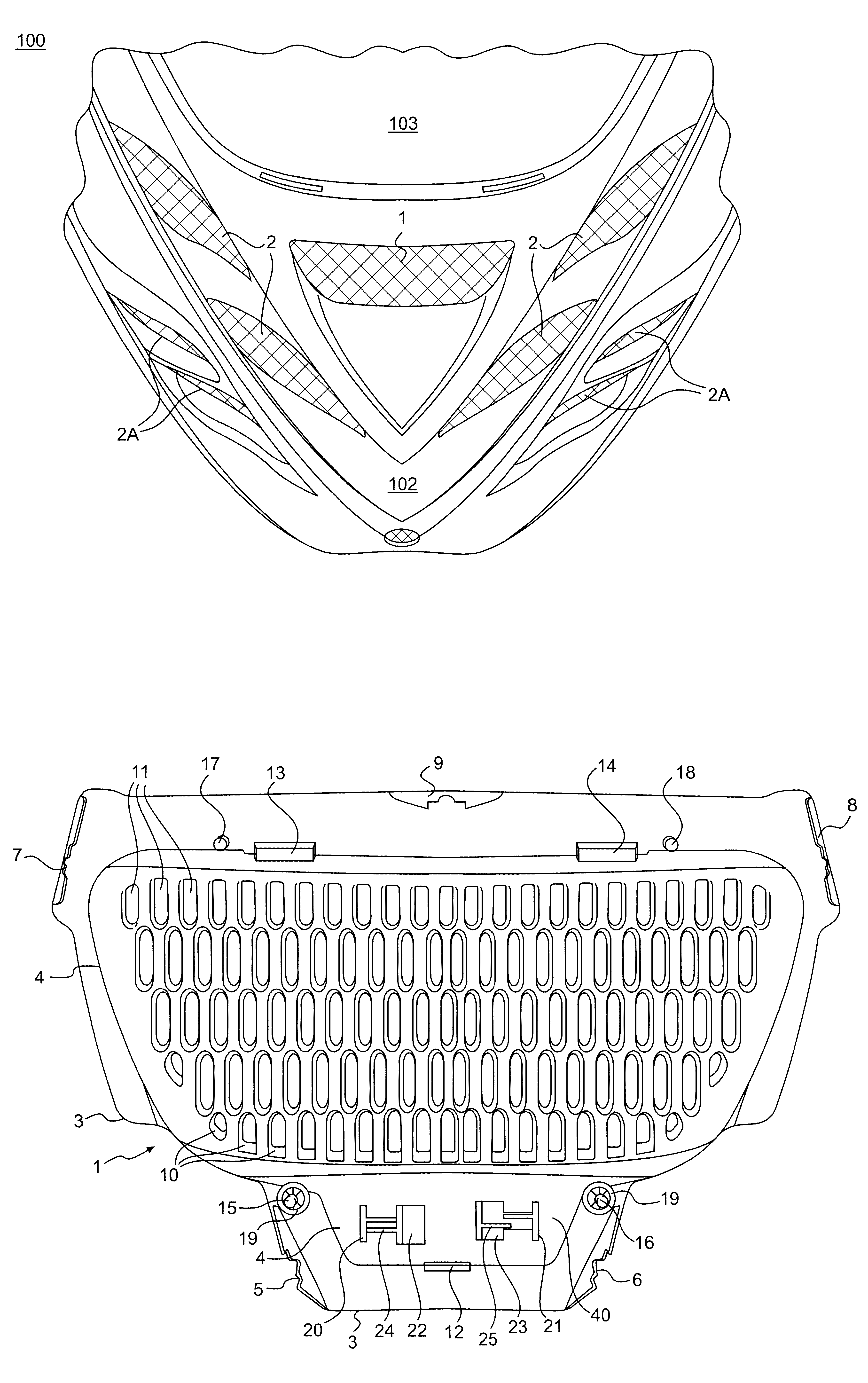
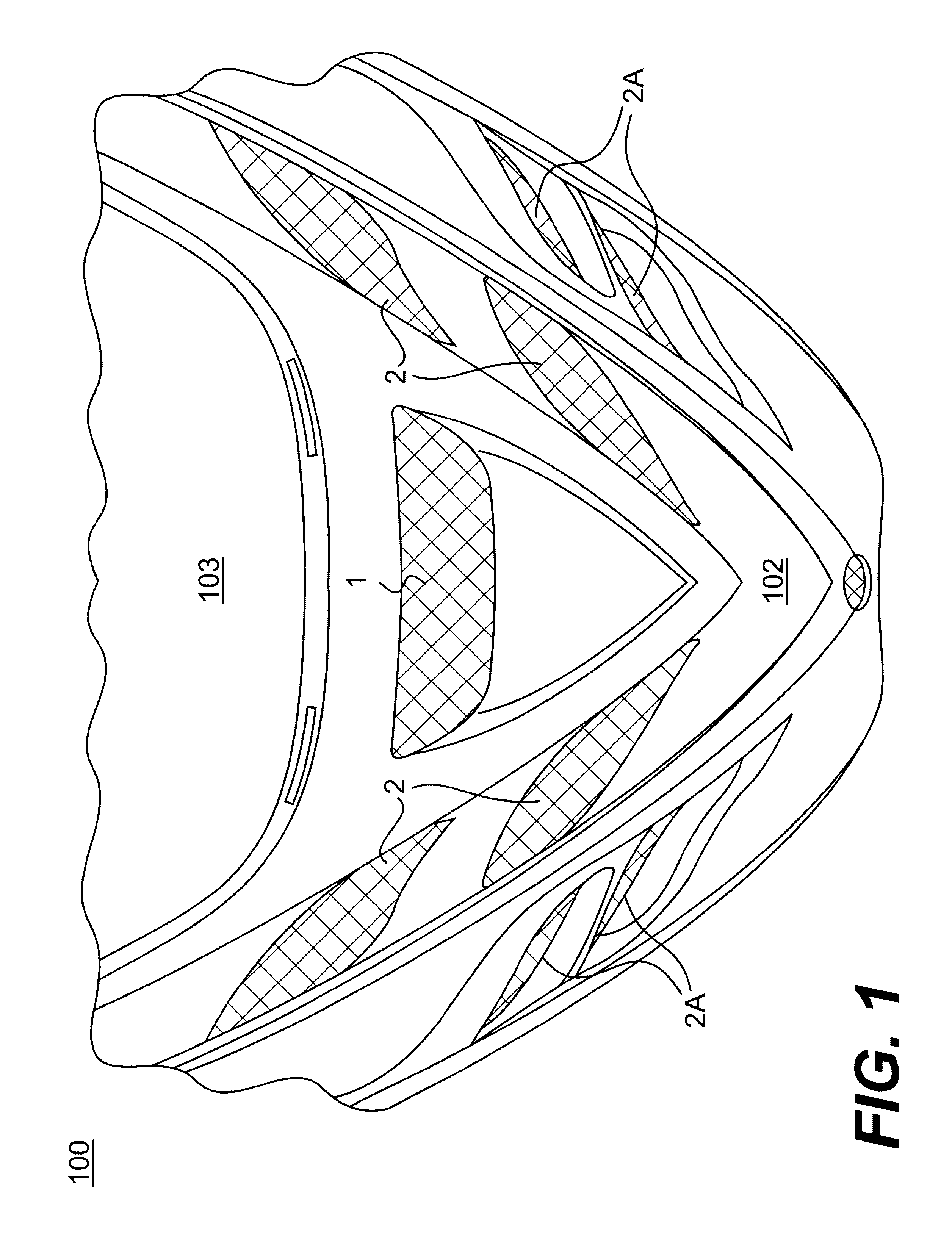
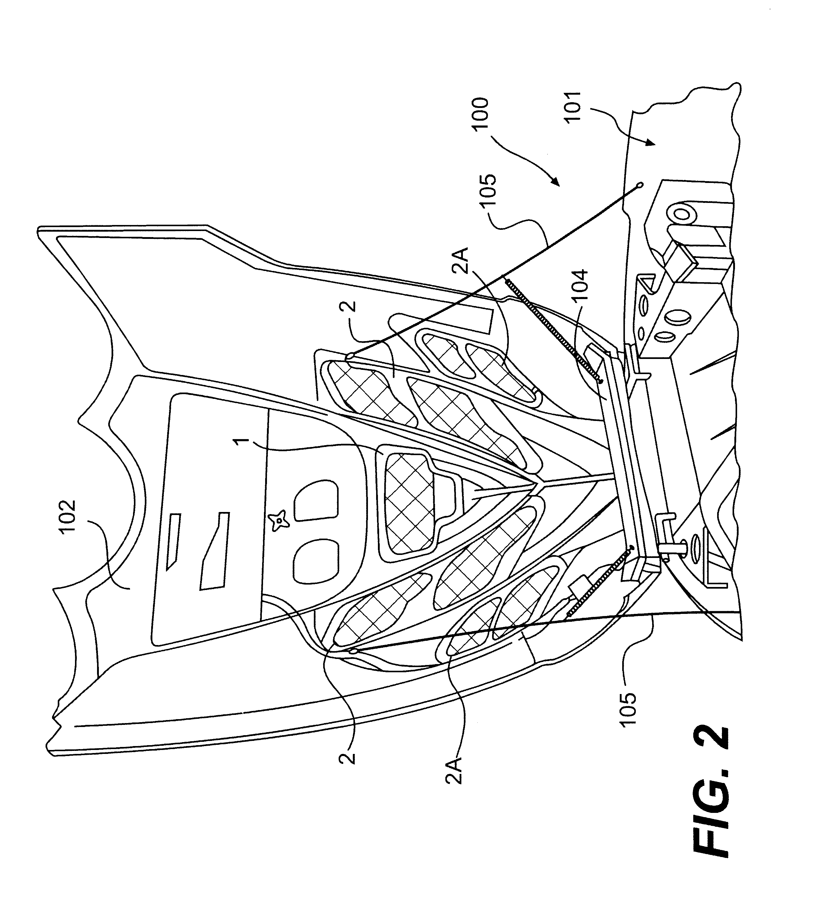
the invention is shown in FIGS. 5 and 6. The second embodiment is a double sliding adjustable air vent shown generally as 2. The actuators 20, 21, 24 and 25 function in a similar manner as the embodiment shown in FIGS. 3 and 4 with the exception that there are four pairs of such actuators. Two pairs function for each sliding grill 27 and 28. The stationary grill 26 remains one integrally molded piece.

In the embodiment shown in FIGS. 5 and 6, one of the sliding vents such as left sliding grill 27 could be closed as shown in FIG. 6, while the other remains opened as shown in FIG. 5. The stationary grill 26 shown in FIGS. 5 and 6 is fastened to the underside of the hood 102 in positions lateral of either side of the stationary grill 1. In order to fasten outer stationary grill 26 to the hood 102, a lower fastening bracket 29 is used along with three upper fastening brackets 30.

The left sliding grill 27 and right sliding grill 28 are guided for movement on stationary grill 26 by means o...

first embodiment

Right and left sliding grills (28 and 27) are also 10 guided in place by lower slide brackets 33. These slide brackets are integrally molded to stationary grill 26 and protrude upwardly through apertures 33(A), one of which is found in the left sliding grill 27 and one in the right sliding grill 28. The upper guide brackets 34 mark the upper limits for the sliding motion of the right sliding grill 28 and left sliding grill 27. Slide brackets 33 and guide brackets 34 can be molded, as discussed above with respect to the first embodiment, to provide the desired frictional fit.

In operation, the apertures 10 and the apertures 11 are aligned in FIG. 5 and permit air to flow therethrough. In order to close the apertures, on either the right or left sides, the operator, as previously mentioned with regard to FIGS. 3 and 4, simply presses on the outsides of projecting actuators 20 and 24 on the right sliding grill 28 and left sliding grill 27 and the vents will move to the closed position o...


PUM


Abstract

In a snowmobile or other vehicle, ventilation of ambient air to the engine compartment is necessary. However, from time to time when encountering deep snow or extremely cold temperatures, it may be necessary to restrict the inflow of ambient air into the engine compartment. An adjustable air vent having a sliding ventilation grill adjusts the air flow. The air vent has actuators for adjusting the air flow that are simple and easily manually operable by an operator even when wearing gloves or mittens without the need of any tools.

Description

BACKGROUND OF THE INVENTION1. Field of the InventionThis invention relates to ventilation systems for vehicles, and in particular, to adjustable air vents for snowmobiles for adjusting an amount of ambient air permitted to flow into engine compartments of the snowmobiles.2. Description of the Related ArtRecreational vehicles and more particularly snowmobiles, generally operate in cooler ambient temperatures. As such, air cooled engines (usually 2 cycle) are often used as a power source. In some newer models of snowmobiles, liquid cooled engines (either 2-cycle or 4 cycle) having heat exchangers are also used. It is generally necessary to have an inflow of air (called “ram air”) into the engine compartment to either cool the heat exchanger for the liquid cooled engine or to flow pass and remove heat from the cooling fins of the air cooled engine.It has been found, however, that when the snowmobile operates at extremely cold temperatures, the engine can be so overcooled by the inflow ...

Claims


Application Information

Patent Timeline
IPC IPC(8): B60K11/00B60K11/08B62J17/02B62J17/00F01P7/10F01P7/00
CPCB60K11/085F01P7/10B62J17/02Y02T10/88B60Y2200/252
Inventor VAILLANCOURT, CLAUDEBORDELEAU, GHYSLAINCHARBONNEAU, CAROLINEBOYER, JEAN-PIERRE
Owner BOMBARDIER RECREATIONAL PROD INC
Why Eureka
Try Eureka