Electro-hydraulic thrust reverser lock actuation system and method

a technology of electrohydraulic thrust reverser and lock actuation, which is applied in the direction of machines/engines, lighter-than-air aircraft, transportation and packaging, etc., can solve the problems of system drawbacks, insufficient landing gear brakes and aerodynamic drag (e.g., flaps, spoilers, etc.) of aircraft, and achieves small and lightweight

Inactive Publication Date: 2005-02-01
HONEYWELL INT INC
View PDF14 Cites 5 Cited by
  • Summary
  • Abstract
  • Description
  • Claims
  • Application Information

AI Technical Summary

Benefits of technology

The present invention provides an electro-hydraulic thrust reverser lock actuation system and method. The lock actuation system does not use large solenoids or motors, and is relatively small and lightweight as compared to many fully electric counterpart systems.

Problems solved by technology

When a jet-powered aircraft lands, the landing gear brakes and aerodynamic drag (e.g., flaps, spoilers, etc.) of the aircraft may not, in certain situations, be sufficient to slow the aircraft down in the required amount of runway distance.
Although safe and reliable, many hydraulic systems and components have exhibited small amounts of leakage, resulting in the need for periodic clean up.
Although electrical thrust reverser actuation systems are safe, reliable, and robustly designed, these systems also exhibit certain drawbacks.
These large solenoids and dedicated motors can increase overall system size envelope, and overall system weight, both of which can lead to increased implementation costs.

Method used


Image

  • Electro-hydraulic thrust reverser lock actuation system and method
  • Electro-hydraulic thrust reverser lock actuation system and method
  • Electro-hydraulic thrust reverser lock actuation system and method

Examples


Embodiment Construction

Before proceeding with the detailed description, it is to be appreciated that the described embodiment is not limited to use in conjunction with a specific thrust reverser system design. Thus, although the description is explicitly directed toward an embodiment that is implemented in a cascade-type thrust reverser system, in which transcowls are used as the moveable thrust reverser component, it should be appreciated that it can be implemented in other thrust reverser actuation system designs, including those described above and those known now or hereafter in the art.

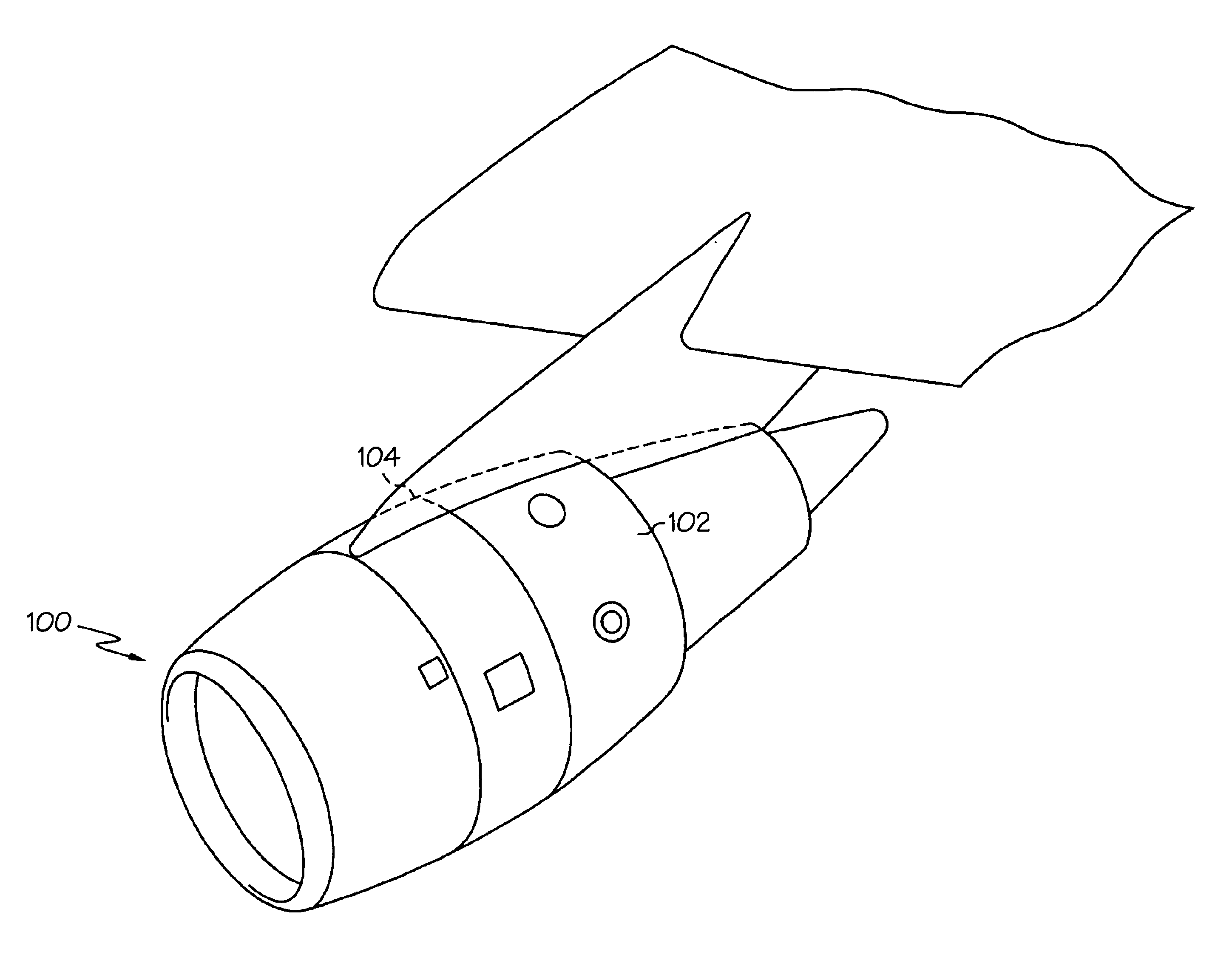
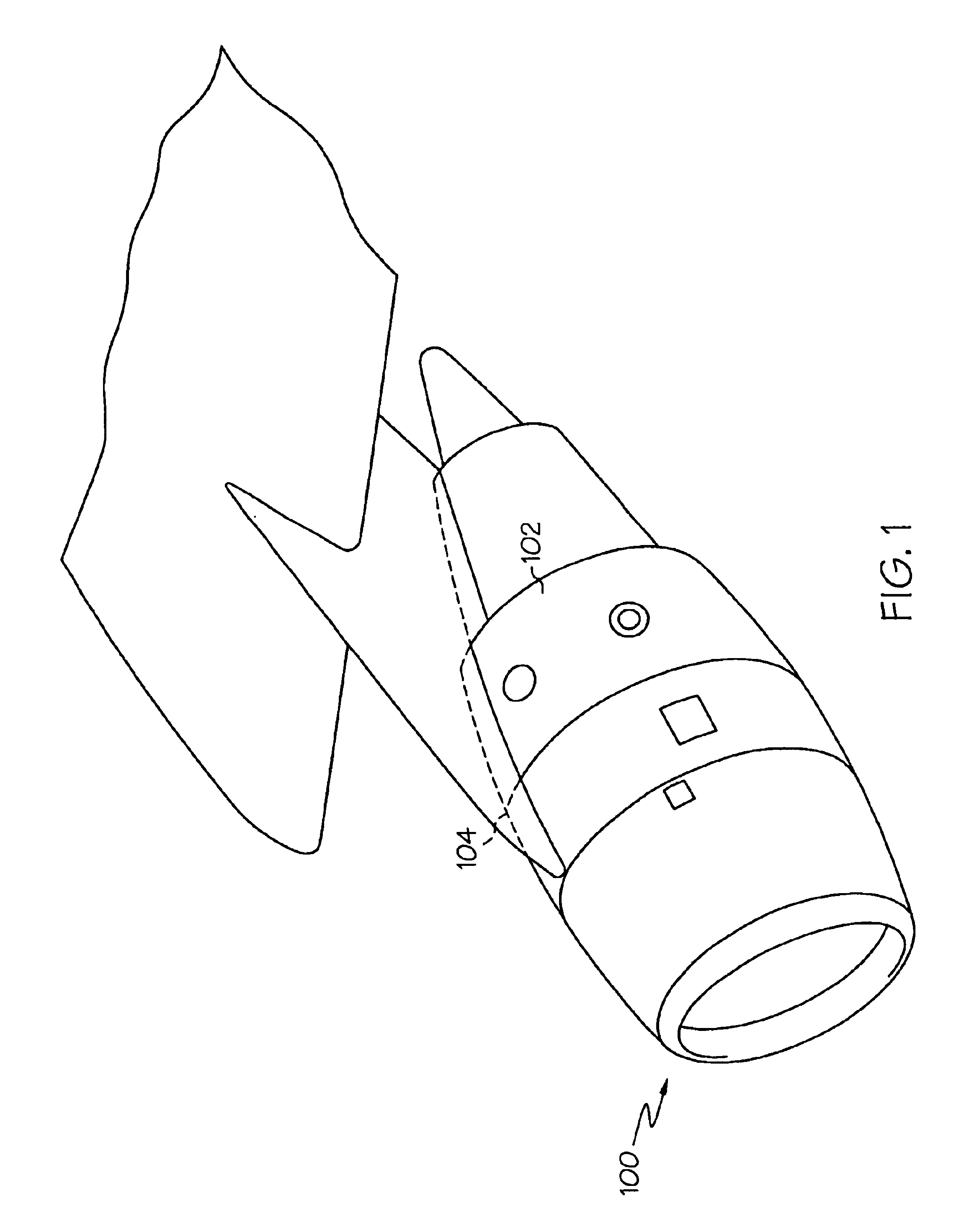
Turning now to the description, and with reference first to FIG. 1, a perspective view of portions of an aircraft jet engine fan case 100 that incorporates a cascade-type thrust reverser is depicted. The engine fan case 100 includes a pair of semi-circular transcowls 102 and 104 that are positioned circumferentially on the outside of the fan case 100. The transcowls 102 and 104 cover a plurality of non-illustrated casc...


PUM


Abstract

An electro-hydraulic thrust reverser lock actuation system includes a hydraulic fluid source and a lock actuator assembly that is configured to selectively pressurize the hydraulic fluid. The lock actuator assembly is adapted to receive a lock control signal and, in response, pressurize the hydraulic fluid in the hydraulic fluid source. One or more lock assemblies are in fluid communication with the hydraulic fluid source and are configured, in response to the hydraulic fluid pressurization, to move to one of a locked or an unlocked position.

Description

FIELD OF THE INVENTIONThe present invention relates to aircraft engine thrust reverser actuation systems and, more particularly, to a thrust reverser lock actuation system that is implemented using electro-hydraulic components.BACKGROUND OF THE INVENTIONWhen a jet-powered aircraft lands, the landing gear brakes and aerodynamic drag (e.g., flaps, spoilers, etc.) of the aircraft may not, in certain situations, be sufficient to slow the aircraft down in the required amount of runway distance. Thus, jet engines on most aircraft include thrust reversers to enhance the braking of the aircraft. When deployed, a thrust reverser redirects the rearward thrust of the jet engine to a generally or partially forward direction to decelerate the aircraft. Because at least some of the jet thrust is directed forward, the jet thrust also slows down the aircraft upon landing.Various thrust reverser designs are commonly known, and the particular design utilized depends, at least in part, on the engine m...

Claims


Application Information

Patent Timeline
Patent Type & Authority Patents(United States)
IPC IPC(8): F02K1/76F02K1/00
CPCF02K1/766F05D2260/406Y02T50/671Y02T50/60
Inventor CHRISTENSEN, DONALD J.
Owner HONEYWELL INT INC
Why Eureka
Try Eureka