System of bendable strips with connectors

a technology of connectors and bendable strips, which is applied in the field of system of bendable strips, can solve the problems of difficult untying, no rigidity of ropes, and too long rope pieces, and achieve the effects of eliminating the need to know how to tie knots, convenient storage, and simple us

Inactive Publication Date: 2005-02-01
ABC PATENT CORP
View PDF16 Cites 39 Cited by
  • Summary
  • Abstract
  • Description
  • Claims
  • Application Information

AI Technical Summary

Benefits of technology

The present invention provides a tying system which is simple to use, for people of all ages and physical agility. The present invention can be used for tying, fastening, carrying, bundling, hanging, and organizing various objects, particularly household, automobile, boating, lawn and garden, sp...

Problems solved by technology

However, often a piece of rope is too long, with ends which need to be tied off or wrapped during use to prevent tangling.
Use of ropes requires knowledge in tying knots, which can later be difficult to untie.
Further, ropes have no “rigidity”.
Such products are limited in application.
They cannot hold their shape durin...

Method used


Image

  • System of bendable strips with connectors
  • System of bendable strips with connectors
  • System of bendable strips with connectors

Examples


second embodiment

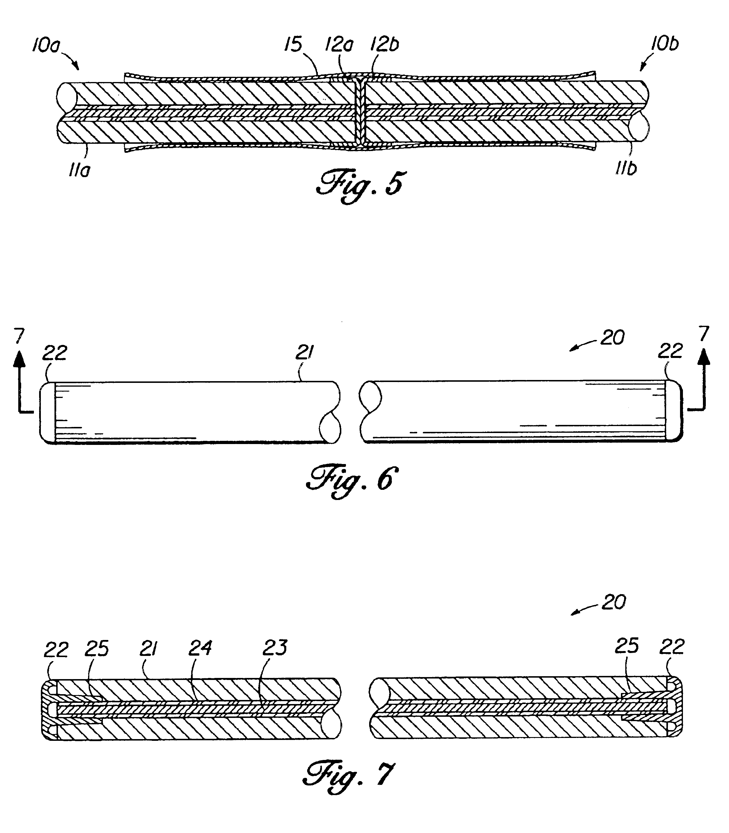
In FIG. 6, the bendable strip 20 is shown, with a plastic end cap 22 at each end, the perimeter of the end caps 22 being flush with the outer surface of the exterior layer 21 of durable, dense foam material.

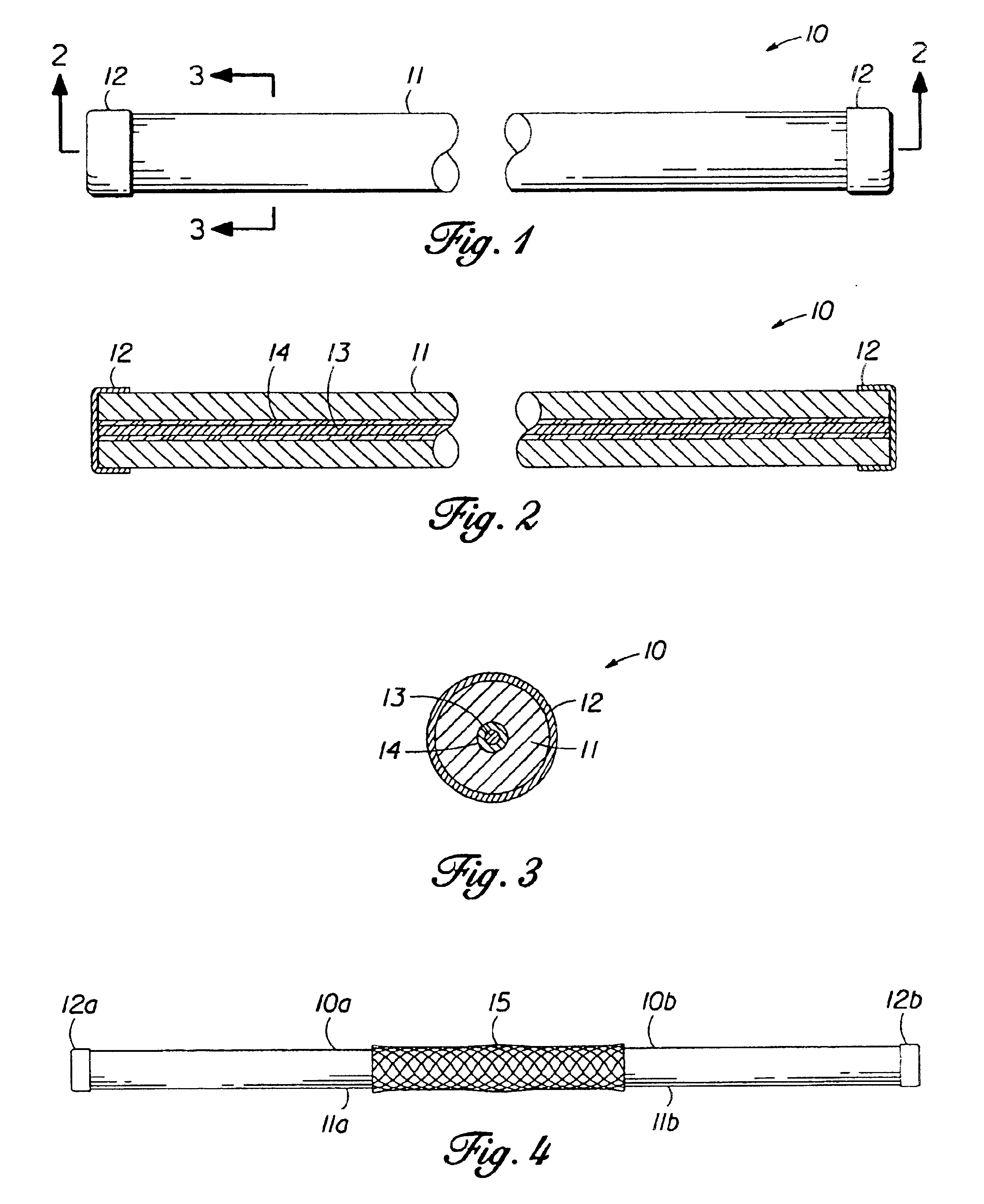
The cross-sectional view of FIG. 7 shows the wire 23 running lengthwise inside the foam layer 21 of the bendable strip 20. The wire 23 can be coated with a flexible, plastic layer 24 to increase the durability of the product. Though not shown, two or more coated wires can be arranged parallel to each other at the core of the bendable strip 20 for added strength and resistance. Each end cap 22 has a hollow shaft 25 extending therefrom, which has been installed over the end of the wire 23 and held in place with glue; by heating / melting the inside of the shaft 25; or by machining the inside of the shaft 25 to lock onto the wire 23. The connector 15 shown in FIG. 4 can be used to join two or more bendable strips 20 in a straight line, or one or more bendable strips 20 can be formed i...

third embodiment

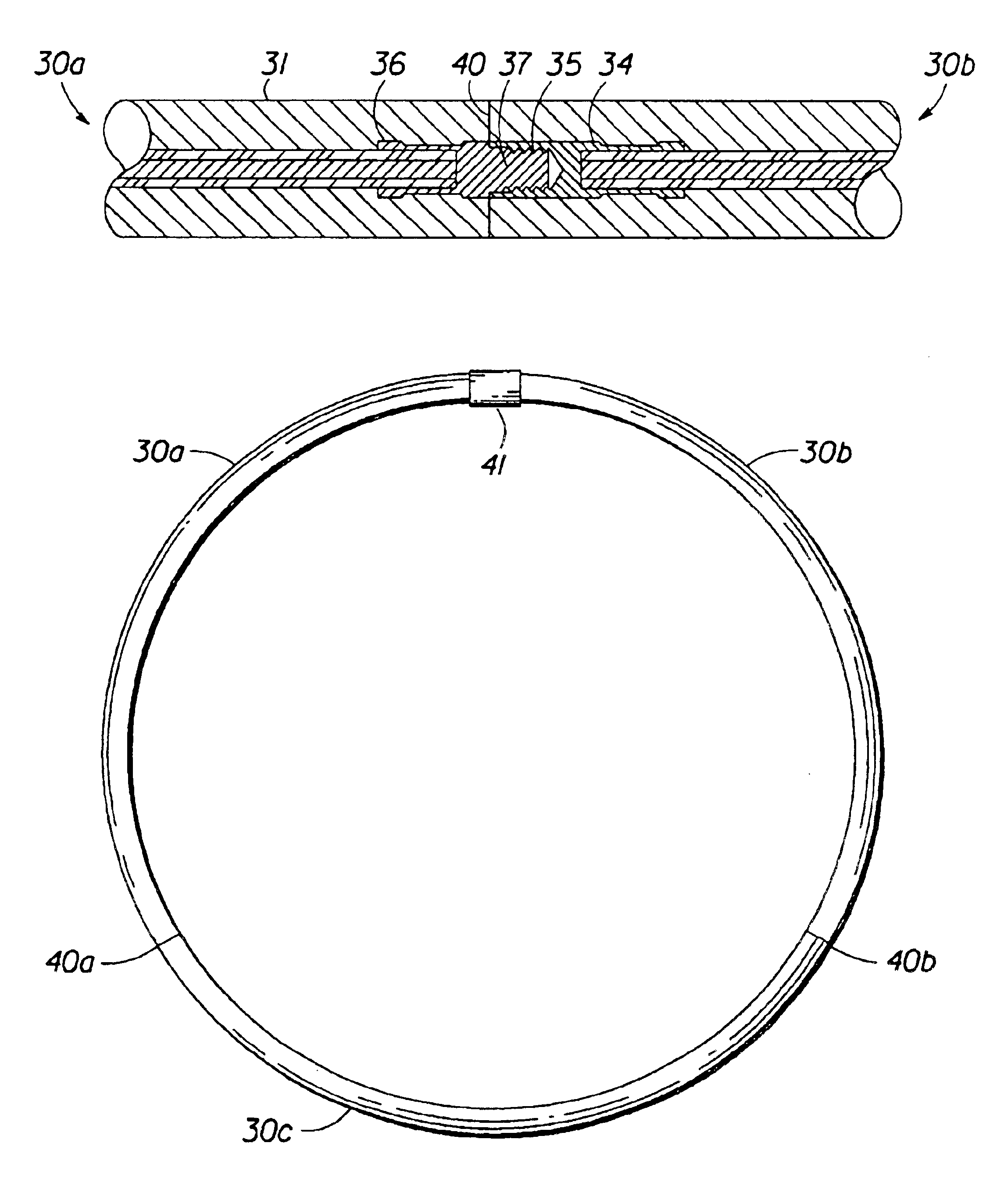
In FIG. 8, the cross-sectional view of the bendable strip 30 is shown. The exterior foam layer 31 surrounds a wire 32, which can be coated with plastic layer 33, for increased durability. A female threaded ferrule 34 with female threaded end 35 is crimped over the coated wire 32 on one end of the bendable strip 30, and a male threaded ferrule 36 with male threaded end 37 is crimped over the coated wire 32 on the other end of the bendable strip 30. Both ferrules 34, 36 can be made from plastic or metal. A protective male threaded plug 38 can be threaded into the female threaded end 35 of female threaded ferrule 34, and a protective female threaded plug 39 can be threaded over the male threaded end 37 of male threaded ferrule 36.

FIG. 9 shows the bendable strips 30a, 30b joined at 40. The male threaded end 37 of male threaded ferrule 36 has been threaded into the female threaded end 35 of female threaded ferrule 34, making the exterior foam layer 31 of bendable strips 30a, 30b essentia...


PUM


Abstract

A system for hanging, tying and securing articles, comprising bendable strips with an outer layer of foam rubber material having a plastic-coated flexible wire running lengthwise inside. Protective plastic caps can be placed on each end of the strip. The ends of two or more bendable strips can be joined with one or more connectors. Alternatively, the bendable strips can have complementary threaded ends, and two or more of such strips can be joined together. An adapter can be used to complete a circular configuration. The system can be sold in a package containing bendable strips, connectors, protective caps and cutters.

Description

BACKGROUND OF THE INVENTIONThe present invention relates to a system of bendable strips of foam-encased wiring with connectors for providing longer strips. The strips can be used for tying, fastening, bundling, hanging, organizing, and carrying various objects.Presently, rope is the most common material in use for tying or hanging objects. However, often a piece of rope is too long, with ends which need to be tied off or wrapped during use to prevent tangling. Use of ropes requires knowledge in tying knots, which can later be difficult to untie. Rope itself does not present a “finished” look when used for tying or hanging. Further, ropes have no “rigidity”.Rigid products such as pre-formed hangers or fasteners made from aluminum wire, steel, or plastic, are used to make plant hangers, bike racks, or garage organizers. Each such item, having a particular shape and design, is typically suitable for only one particular use.Other tying and fastening products on the market for use in tyi...

Claims


Application Information

Patent Timeline
IPC IPC(8): A01G9/12B65D63/00F16G11/00F16G11/08
CPCA01G9/128F16G11/08B65D63/00
Inventor OLIVE, GARY L.
Owner ABC PATENT CORP
Why Eureka
Try Eureka