Three-dimensional axial-flow turbine stage

a technology of axial flow turbine and stage, which is applied in the direction of machines/engines, liquid fuel engines, other chemical processes, etc., can solve the problems of reducing the performance of the stage, affecting the efficiency of the turbine, and increasing the loss of blade elements, so as to reduce the adverse effect of interferen

Inactive Publication Date: 2005-02-01
KK TOSHIBA
View PDF7 Cites 4 Cited by
  • Summary
  • Abstract
  • Description
  • Claims
  • Application Information

AI Technical Summary

Benefits of technology

The present invention has been made in view of such circumstances and it is therefore an object of the present invention to reduce the adverse effec

Problems solved by technology

Thus, the energy of the working fluid is dissipated in generating such secondary flow vortices, resulting in the reduction of turbine performance.
When the inclination increases beyond a limit angle, the flow of the working fluid along a middle part of the blade decreases, the flow of the same along the end wall 7 increases and, consequently, the performance of the stage is deteriorated.
However, since the pressure difference between

Method used


Image

  • Three-dimensional axial-flow turbine stage
  • Three-dimensional axial-flow turbine stage
  • Three-dimensional axial-flow turbine stage

Examples


Embodiment Construction

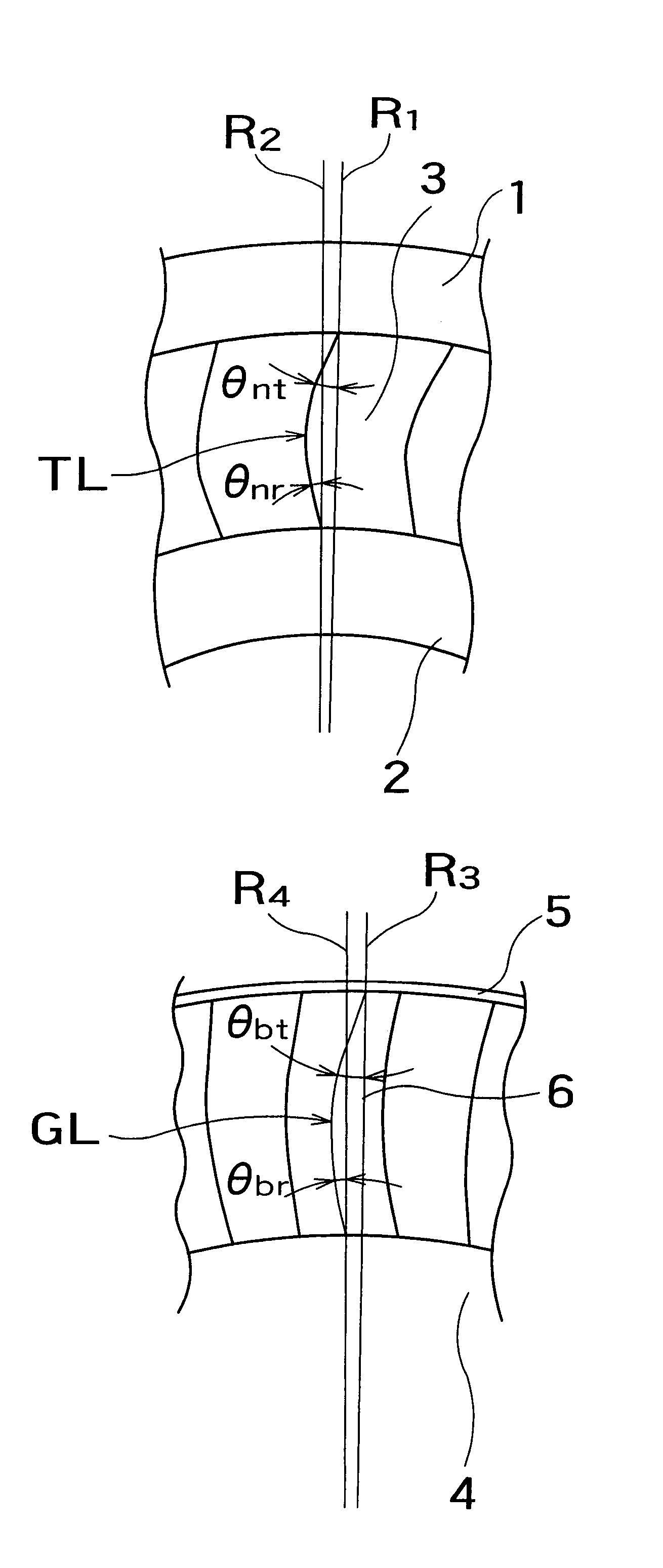
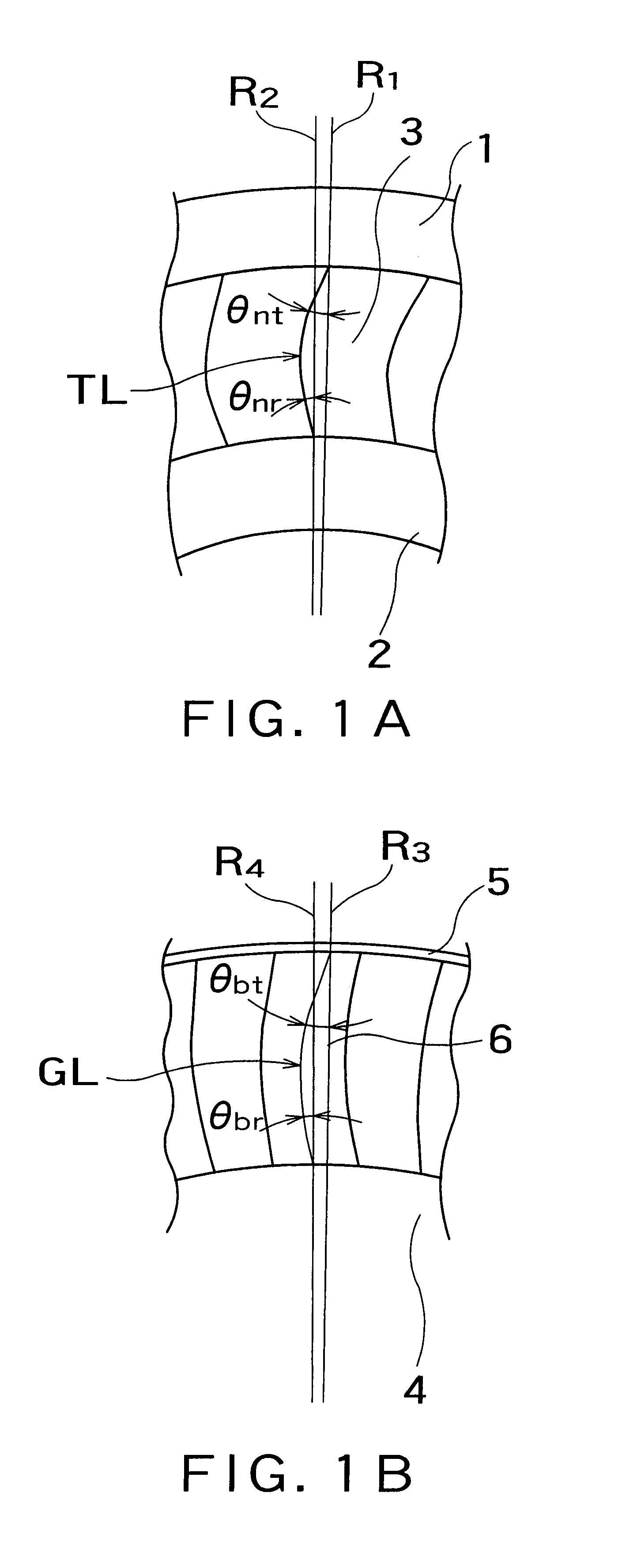
An axial-flow turbine stage embodying the present invention will be described with reference to the accompanying drawings. FIGS. 1A and 1B show an axial-flow turbine stage in a first embodiment according to the present invention. FIG. 1A is a view of a stationary blade 3 taken in the axial direction from the outlet side, and FIG. 1B is a view of a moving blade 6 taken in the axial direction from the outlet side.

A plurality of stationary blades 3 are arranged in a circumferential arrangement abut the axis, not shown, of a rotor shaft 4 shown in FIG. 1B. The stationary blades 3 are fixed to an outer ring 1 and an inner ring 2. As shown in FIG. 1A, each stationary blade 3 has a trailing edge TL convex toward a face side with respect to radial lines R1 and R2 radially extending from the axis of the rotor shaft 4

In this specification, the expression “the trailing edge TL of the stationary blade is convex toward a face side with respect to radial lines” signifies a state where the shape o...


PUM


Abstract

An object of the present invention is to reduce the adverse effect of interference between stationary blades and moving blades on the performance of an axial-flow turbine and to provide a high-performance turbine stage. Each of the stationary blades has a trailing edge convex toward a face side with respect to a radial line radially extending from the axis of the rotor shaft, and the each of the moving blades has a blade center-of-gravity line convex toward the face side with respect to a radial line radially extending from the axis of the rotor shaft, and shapes of the stationary blades and the moving blades meet conditions expressed by:
1<θnrnt
1<θbtbr
where, θnt and θnr are angles between the stationary blade tip and the stationary blade root, and radial lines, and θbt and θbr are angles between the blade center-of-gravity line of the moving blade at the tip of the same, and the blade center-of-gravity line of the moving blade at the tip of the moving blade, and radial lines.

Description

TECHNICAL FIELDThe present invention relates to an axial-flow turbine and, more particularly, to a turbine stage capable of greatly improving turbine efficiency.BACKGROUND ARTInsurance of reliability and enhancement of efficiency are important subject relating to axial-flow turbines for power plants from the point of view of environmental problems and saving energy.Generally, in an axial-flow turbine, such as a steam turbine, a turbine stage is composed of: a plurality of stationary blades 3 fixedly arranged between a nozzle outer ring 1 and a nozzle inner ring 2; and a plurality of moving blades 6 fixedly mounted on a rotor shaft 4 and having tip portions each connected to a shroud 5. One or more turbine stages are axially arranged to form a steam turbine. Recently, a three-dimensional blade has been proposed to improve the efficiency of a turbine through the improvement of the aerodynamic performance of stationary and dynamic blade elements.The advantage of the conventional three-...

Claims


Application Information

Patent Timeline
IPC IPC(8): F01D5/14F01D9/02
CPCF01D5/142Y10S416/05F05D2250/20
Inventor KAWASAKI, SAKAE
Owner KK TOSHIBA
Why Eureka
Try Eureka