Timing measurement device using a component-invariant vernier delay line

a timing measurement and delay line technology, applied in the field of high-resolution timing measurements, can solve the problems of inability to eliminate complete errors in cdf or histogram collection, affecting the accuracy of measurement, so as to achieve the effect of reducing the measurement tim

Inactive Publication Date: 2005-02-01
MCGILL UNIV
View PDF3 Cites 35 Cited by
  • Summary
  • Abstract
  • Description
  • Claims
  • Application Information

AI Technical Summary

Benefits of technology

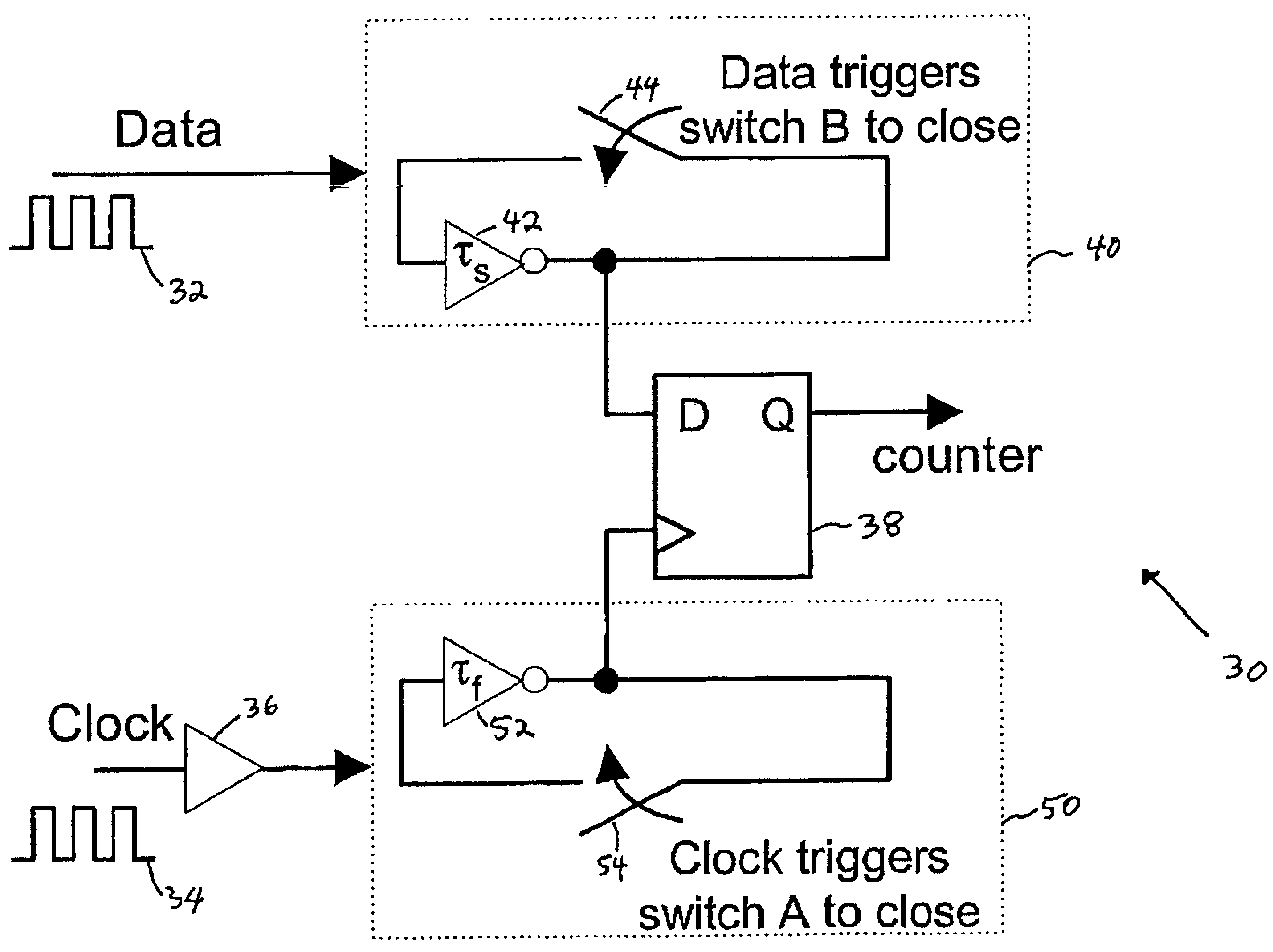
Accordingly, an object of the present invention is to avoid the dependency on element matching of prior art timing and jitter measurement devices by providing a component-invariant VDL structure. Thus, the present invention provides a single-stage VDL structure, which is used to mimic the behavior of a complete VDL. This is accomplished by feeding the output of one stage of a VDL back to its input. In fact, this is equivalent to having two oscillators running simultaneously with different frequencies to produce a constant delay difference during every cycle of oscillation. By extending the circuit structure to include multiple oscillators, measurement time is reduced by a factor equivalent to the number of additional oscillators.

Problems solved by technology

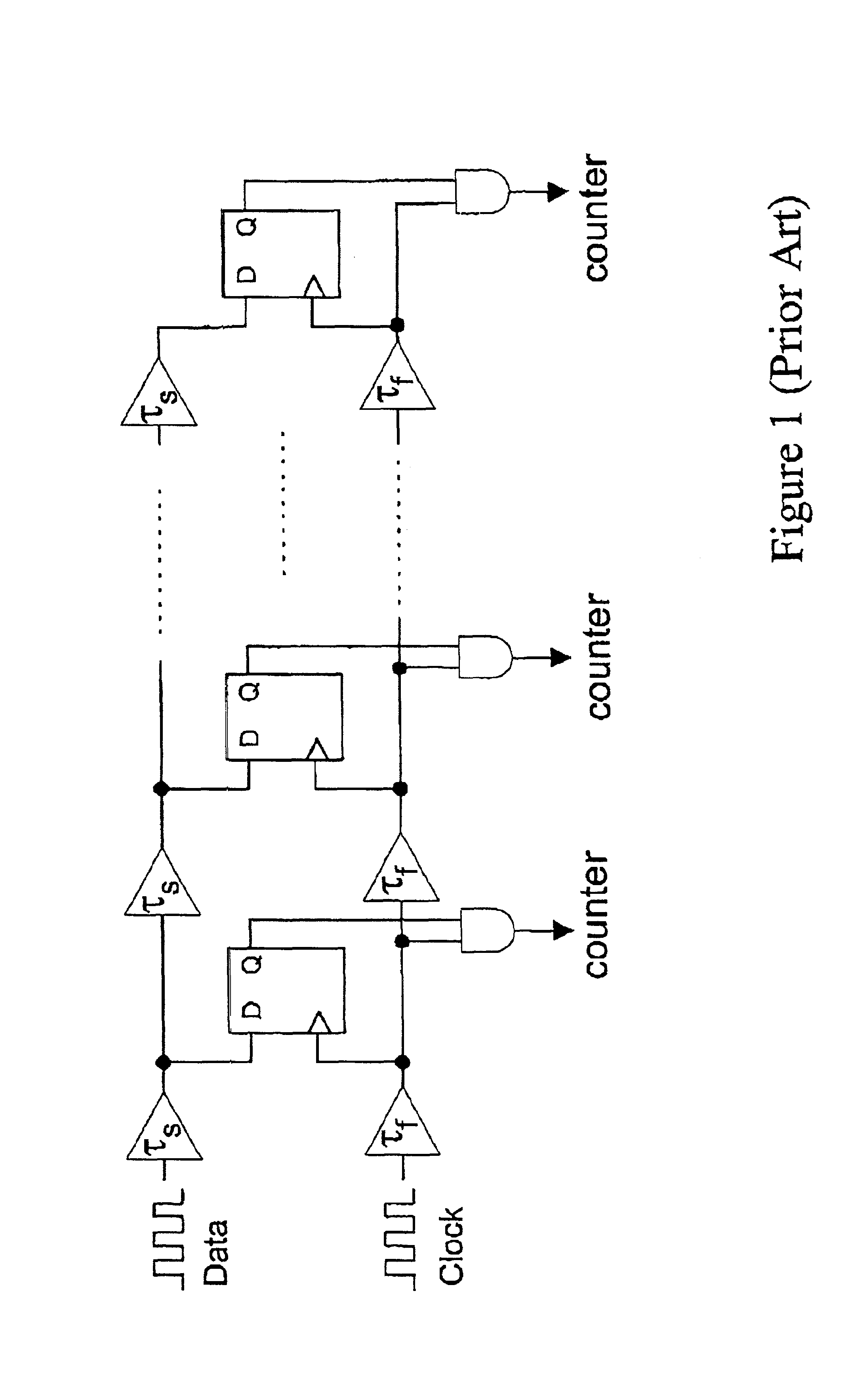
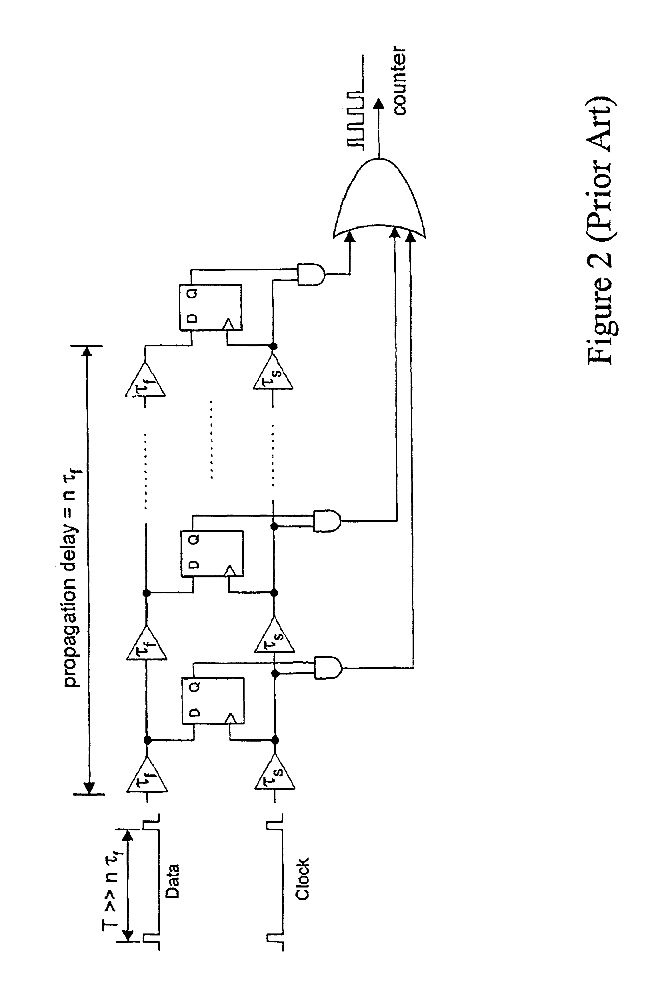
An important drawback to the prior art VDL structures shown in FIGS. 1 and 2 is that measurement accuracy depends on the matching of delay elements between successive stages.
Mismatches in delay elements can lead to errors in the CDF or histogram collected.
Although careful layout techniques may help in minimizing these mismatches, they cannot eliminate them completely.
Unfortunately, however, the reported design still depends largely on the matching of pairs of delay elements.

Method used


Image

  • Timing measurement device using a component-invariant vernier delay line
  • Timing measurement device using a component-invariant vernier delay line
  • Timing measurement device using a component-invariant vernier delay line

Examples


Embodiment Construction

Current timing and jitter measurement devices employing VDL techniques generally require highly matched elements in order to reduce differential non-linearity timing errors. In order to remove this dependency on element matching, the present invention provides a component-invariant VDL structure. The measurement device of the present invention is based on a single-stage VDL structure, which is used to mimic the behavior of a complete VDL. This is accomplished by feeding the output of one stage of a VDL back to its input. In fact, this is equivalent to having two oscillators running simultaneously with different frequencies to produce a constant delay difference during every cycle of oscillation. By extending the circuit structure to include multiple oscillators, measurement, time may be reduced by a factor equivalent to the number of additional oscillators.

FIG. 3 depicts a component-invariant VDL structure 30 according to a first aspect of the present invention. The single-stage VDL...


PUM


Abstract

In recent years, much effort has been placed on improving the performance of timing and jitter measurement devices using Delay Locked Loop (DLL) and Vernier Delay Line (VDL) techniques. However, these approaches require highly matched elements in order to reduce differential non-linearity timing errors. In an attempt to reduce the requirement on element matching, a component-invariant VDL technique is disclosed that enables the measurement device to be synthesized from an RTL description. The present invention is based on a single-stage VDL structure, which is used to mimic the behavior of a complete VDL. Furthermore, as test time is an important consideration during a production test, a method and system is provided that reduces test time at the expense of additional hardware.

Description

MICROFICHE APPENDIXNot Applicable.TECHNICAL FIELDThe present invention relates to high-resolution timing measurements and, in particular, to a timing measurement system and method using a component-invariant Vernier Delay Line.BACKGROUND OF THE INVENTIONAn accurate measure of the jitter characteristics of a signal waveform or, alternatively, a measure of the timing variation between a signal waveform and a reference waveform can yield important information relating to the performance of the source of the signal waveform. Accordingly, the performance of timing and jitter measurement devices is a key factor in being able to accurately characterize the performance of a signal waveform source (e.g. a phase-locked loop). To this end, much recent effort has been devoted to improving the performance and resolution of such timing and jitter measurement devices.Performing a jitter measurement on a data signal with sub-gate resolution can be achieved using two delay chains feeding into the cl...

Claims


Application Information

Patent Timeline
Patent Type & Authority Patents(United States)
IPC IPC(8): G04F10/06G04F10/00G01R29/02
CPCG04F10/06G04F10/00
Inventor ROBERTS, GORDON W.CHAN, ANTONIO H.
Owner MCGILL UNIV
Why Eureka
Try Eureka