Focal-plane shutter for digital still cameras

a shutter and digital still technology, applied in the field of optical plane shutters for digital still cameras, can solve the problems of reducing the possibility of using this shutter unit, affecting the design freedom of the camera, and unable to provide a proper slit for making proper exposure, etc., to achieve the effect of compact design and favorable application

Inactive Publication Date: 2005-02-01
COPAL CO LTD
View PDF7 Cites 20 Cited by
  • Summary
  • Abstract
  • Description
  • Claims
  • Application Information

AI Technical Summary

Benefits of technology

It is, therefore, an object of the present invention to provide a focal-plane shutter for digital still cameras which allows an imaging surface to be exposed through a slit provided by the first blade and the second blade and which is favorably applied to a camera equipped with an electronic view finder and is suitable for compact design.

Problems solved by technology

However, in the digital still camera, particularly provided with the electronic view finder, each of the first blade and the second blade need not necessarily be constructed with a plurality of blade components.
Therefore, in this type, after a cocking operation, a cocking member cannot be restored immediately to an initial position before cock, and after the electromagnet is energized prior to subsequent photography, the cocking member is restored.
However, if the entire shutter unit is enlarged, the number of degrees of camera design freedom will be limited in inverse proportion to shutter size, and the possibility of using this shutter unit will diminish.
Consequently, it is extremely difficult to provide a proper slit for making proper exposure.
Thus, there is a considerable difference between both in biasing force of the driving spring exerted when the edge of the slit crosses the path.
Although the use of driving springs with different specifications is considered, it is very difficult that the shutter is designed to across the optical path AP at the same speed (operation characteristic).
As a result, the upper and lower dimensions of the entire shutter unit cannot be reduced.

Method used


Image

  • Focal-plane shutter for digital still cameras
  • Focal-plane shutter for digital still cameras
  • Focal-plane shutter for digital still cameras

Examples


Embodiment Construction

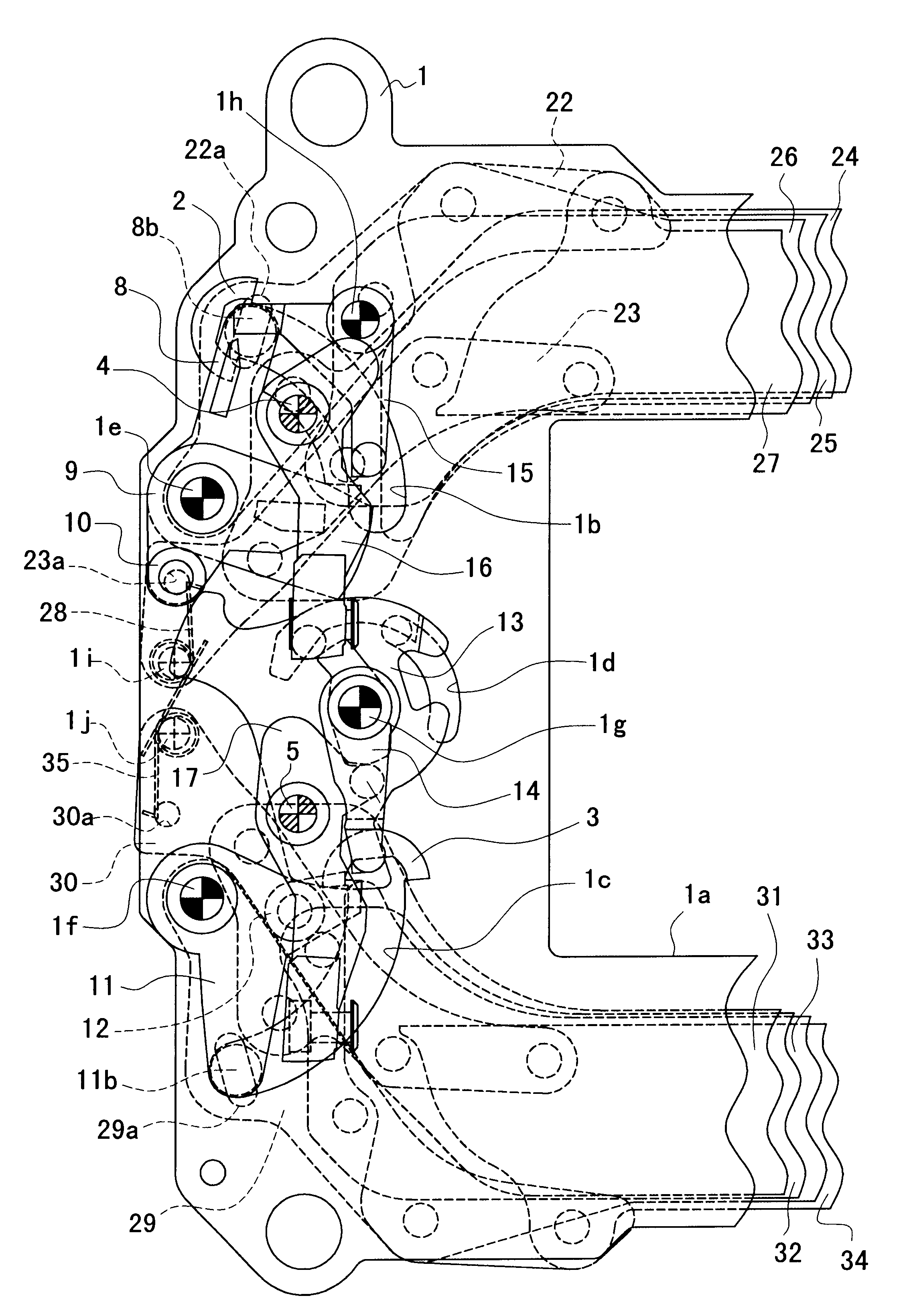
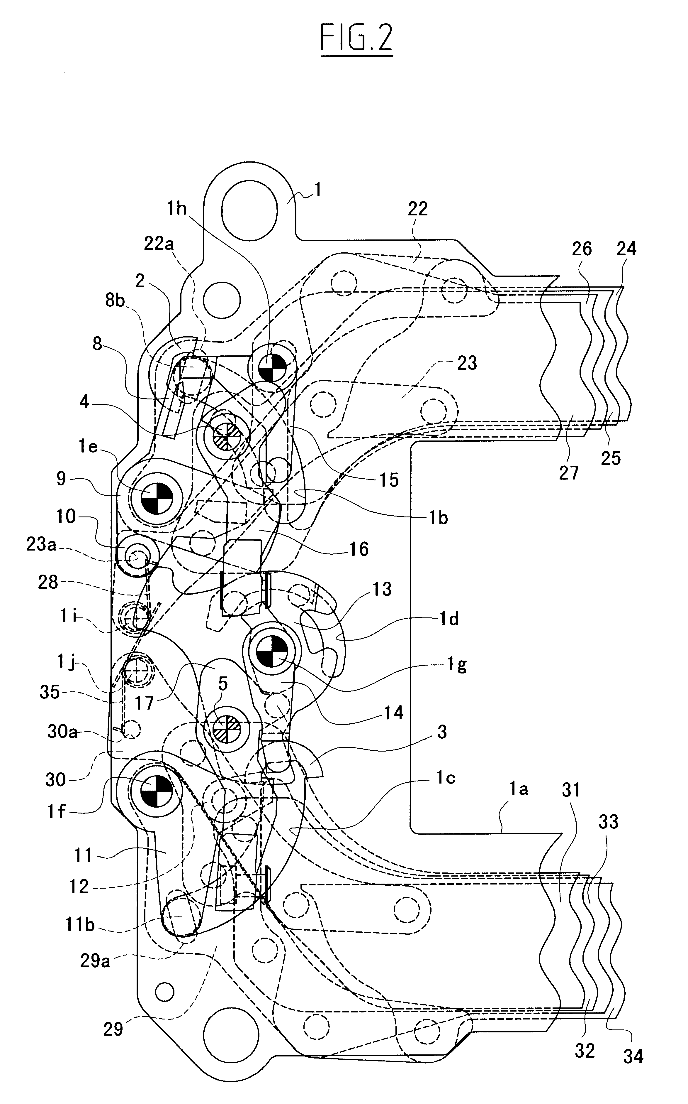
The present invention is applicable to the focal-plane shutter of either the direct type or the locking type and is such that each of the first blade and the second blade can be constructed with a single blade component or a plurality of blade components. The embodiment is the focal-plane shutter of the locking type, in which each of the first blade and the second blade is constructed with a plurality of blade components. The structure of the embodiment is first described below, chiefly using FIGS. 2 and 3. In the following description, the object side of individual members is conveniently referred to as a surface side, and an image sensor (such as a CCD) side as a back side.

As shown in FIG. 2, a shutter base plate 1 is provided with an aperture 1a of a rectangle elongated in a lateral direction at about the middle thereof. Since, as mentioned above, FIG. 2 depicts parts of the shutter on the left side thereof, viewed from the object side, the aperture 1a is also depicted as a part ...


PUM


Abstract

A focal-plane shutter for digital still cameras is constructed so that a first driving member for a first blade connected to the first blade is biased by a cocking spring to rotate clockwise and a second driving member for the first blade is biased by a driving spring to rotate counterclockwise. A driving member for a second blade connected to the second blade is biased by a driving spring to rotate counterclockwise. An exposure aperture is fully opened before photographing, and when a cocking member is rotated in a clockwise direction in photographing, the first driving member is released from the holding of the cocking member and is rotated, and the exposure aperture is covered by the first blade. After that, when releasing members are separated from the iron cores of respective electromagnets, locks of locking members are released, and the driving members are rotated counterclockwise in turn. Consequently, exposure is carried out through a slit formed by the first blade and the second blade.

Description

BACKGROUND OF THE INVENTION1. Field of the InventionThis invention relates to a focal-plane shutter for digital still cameras which is designed to actuate a first blade and a second blade in turn in the same direction when photographing is performed and to expose an imaging surface through a slit provided by both blades.2. Description of Related ArtIn focal-plane shutters used in digital still cameras, some types of shutters are known in accordance with the specifications of cameras. One of them, like a focal-plane shutter used in a film camera, is equipped with a first blade and a second blade to actuate these blades in turn at predetermined timing so that an imaging surface is exposed continuously from its one side to the other through a slit provided by the blades.Digital still cameras using shutters constructed as mentioned above are divided into two classes, those in which an optical finder is provided as in the film camera so that the imaging surface is covered by at least one...

Claims


Application Information

Patent Timeline
Patent Type & Authority Patents(United States)
IPC IPC(8): G03B9/18G03B9/10G03B9/36
CPCG03B9/18
Inventor TAKAHASHI, SHIGEMI
Owner COPAL CO LTD
Why Eureka
Try Eureka