Transflective liquid crystal display device with substrate having greater height in reflective region

a liquid crystal display device and substrate technology, applied in static indicating devices, optics, instruments, etc., can solve the problems of inability to find the optimal structure for forming multiple gaps, high power consumption, and inability to achieve precise and easy control

Inactive Publication Date: 2005-02-01
SHARP KK
View PDF23 Cites 76 Cited by
  • Summary
  • Abstract
  • Description
  • Claims
  • Application Information

AI Technical Summary

Benefits of technology

Moreover, it is possible to precisely and easily control the optical density of the color filter layer located in the reflection region and the thickness of the liquid crystal layer in the reflection region, if the second substrate includes a first transparent dielectric layer for controlling the thickness, existence proportion, etc., of the color filter layer in the reflection region, and a second transparent dielectric layer for controlling the height of the surface of the second substrate in the reflection region.

Problems solved by technology

A transmission type liquid crystal display device, which displays an image by using light from the backlight, is capable of producing a bright display with a high contrast ratio without being substantially influenced by the brightness of the environment, but consumes a lot of power due to the backlight.
Moreover, a transmission type liquid crystal display device has a poor visibility under very bright environments (e.g., when used outdoor under a clear sky).
However, for a liquid crystal display device in which the thickness of the liquid crystal layer in the reflection region is larger than that in the transmission region, i.e., a liquid crystal display device having a so-called “multi-gap structure”, the optimal structure for forming multiple gaps has not yet been discovered.

Method used


Image

  • Transflective liquid crystal display device with substrate having greater height in reflective region
  • Transflective liquid crystal display device with substrate having greater height in reflective region
  • Transflective liquid crystal display device with substrate having greater height in reflective region

Examples


embodiment 1

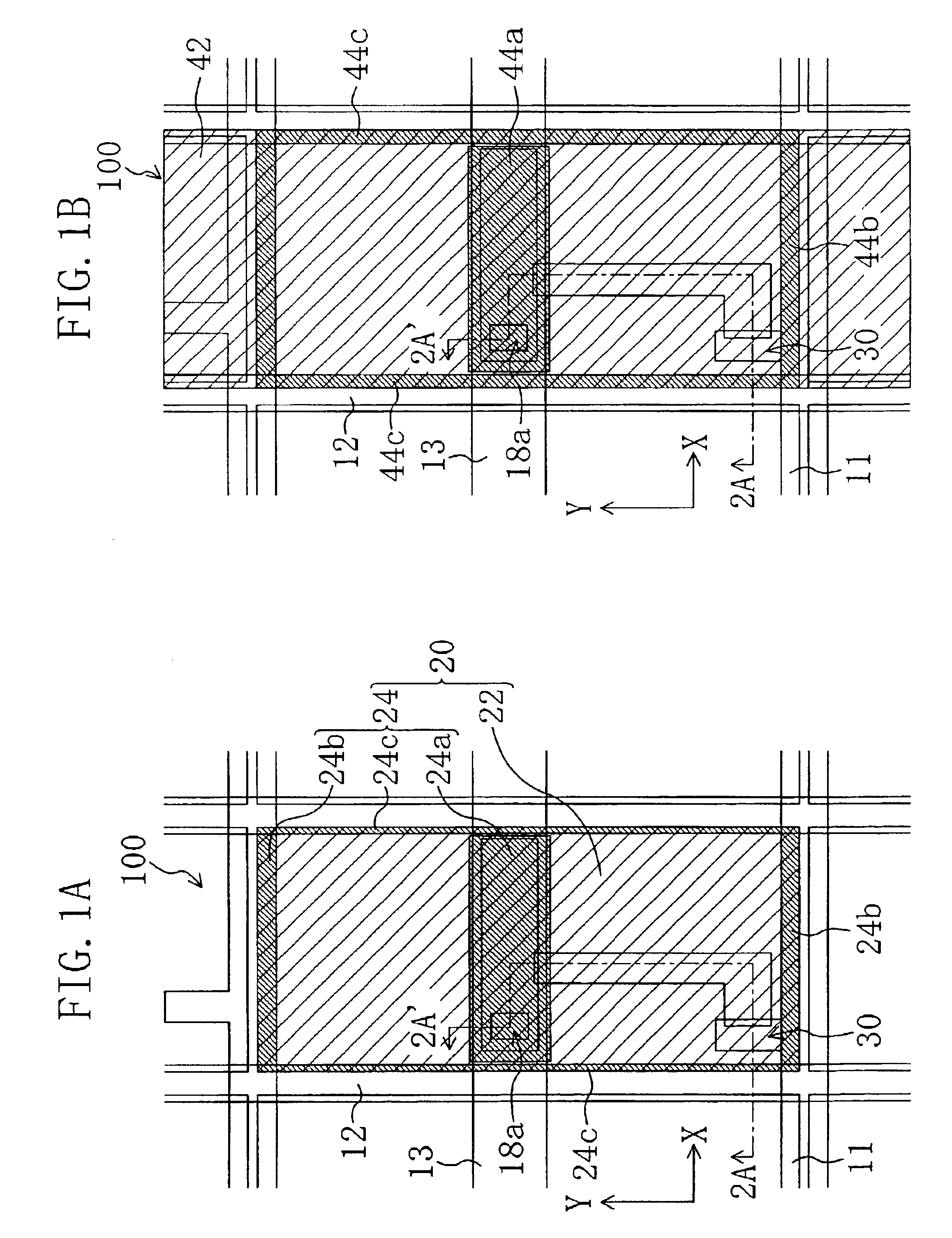
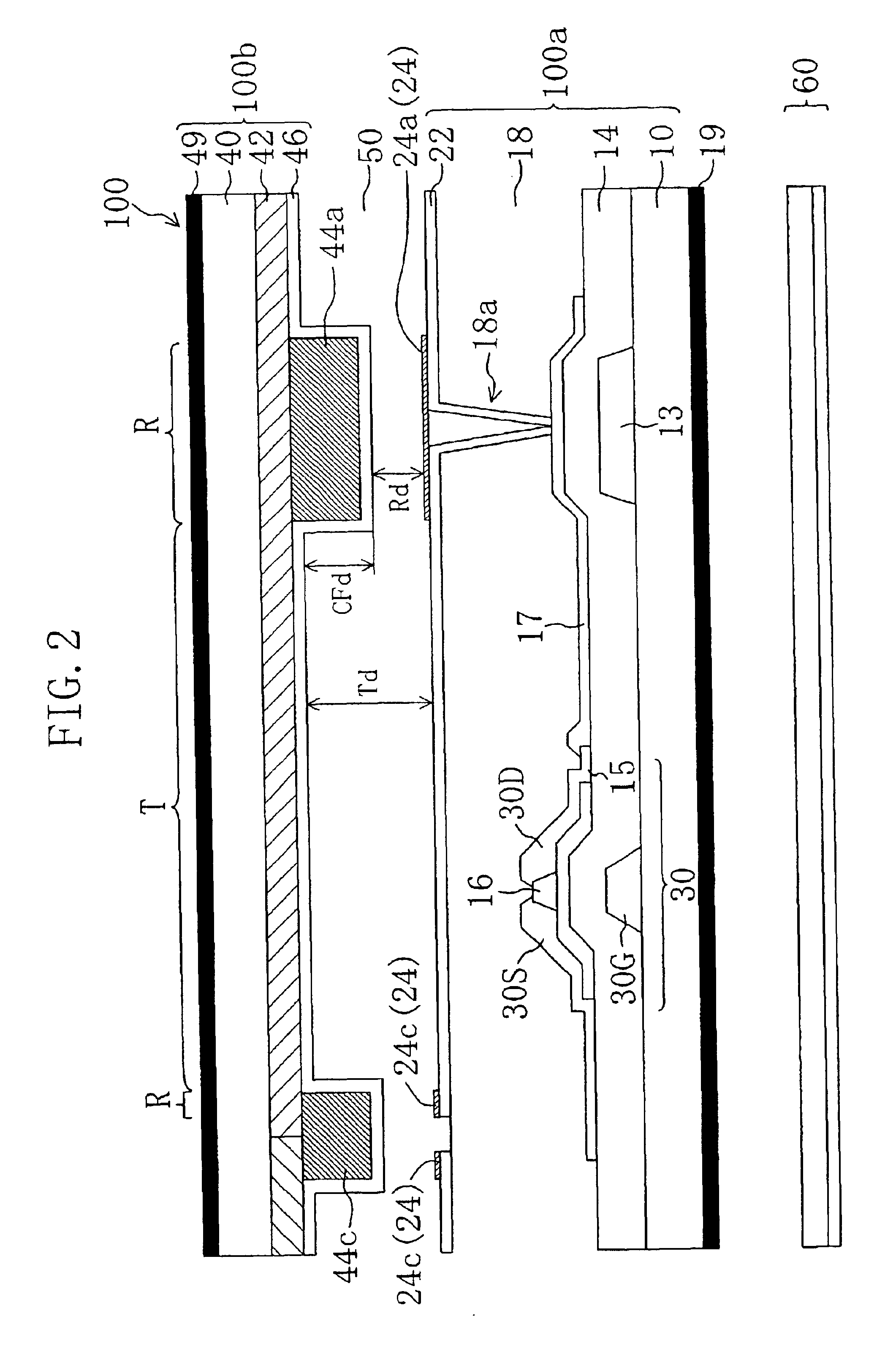
The structure of one picture element region of a liquid crystal display device 100 according to Embodiment 1 of the present invention will be described with reference to FIG. 1A, FIG. 1B and FIG. 2. FIG. 1A and FIG. 1B are plan views schematically illustrating the liquid crystal display device 100, and FIG. 2 is a cross-sectional view taken along line 2A-2A′ in FIG. 1A and FIG. 1B. Note that FIG. 1A is a plan view illustrating an active matrix substrate 100a of the liquid crystal display device 100, and FIG. 1B is a plan view illustrating the active matrix substrate 100a and an opposing counter substrate 100b being attached together. Moreover, in subsequent FIGs, each element having substantially the same function as the corresponding element in the liquid crystal display device 100 will be denoted by the same reference numeral and will not be further described below.

The liquid crystal display device 100 includes the active matrix substrate (hereinafter referred to as “TFT substrate...

embodiment 2

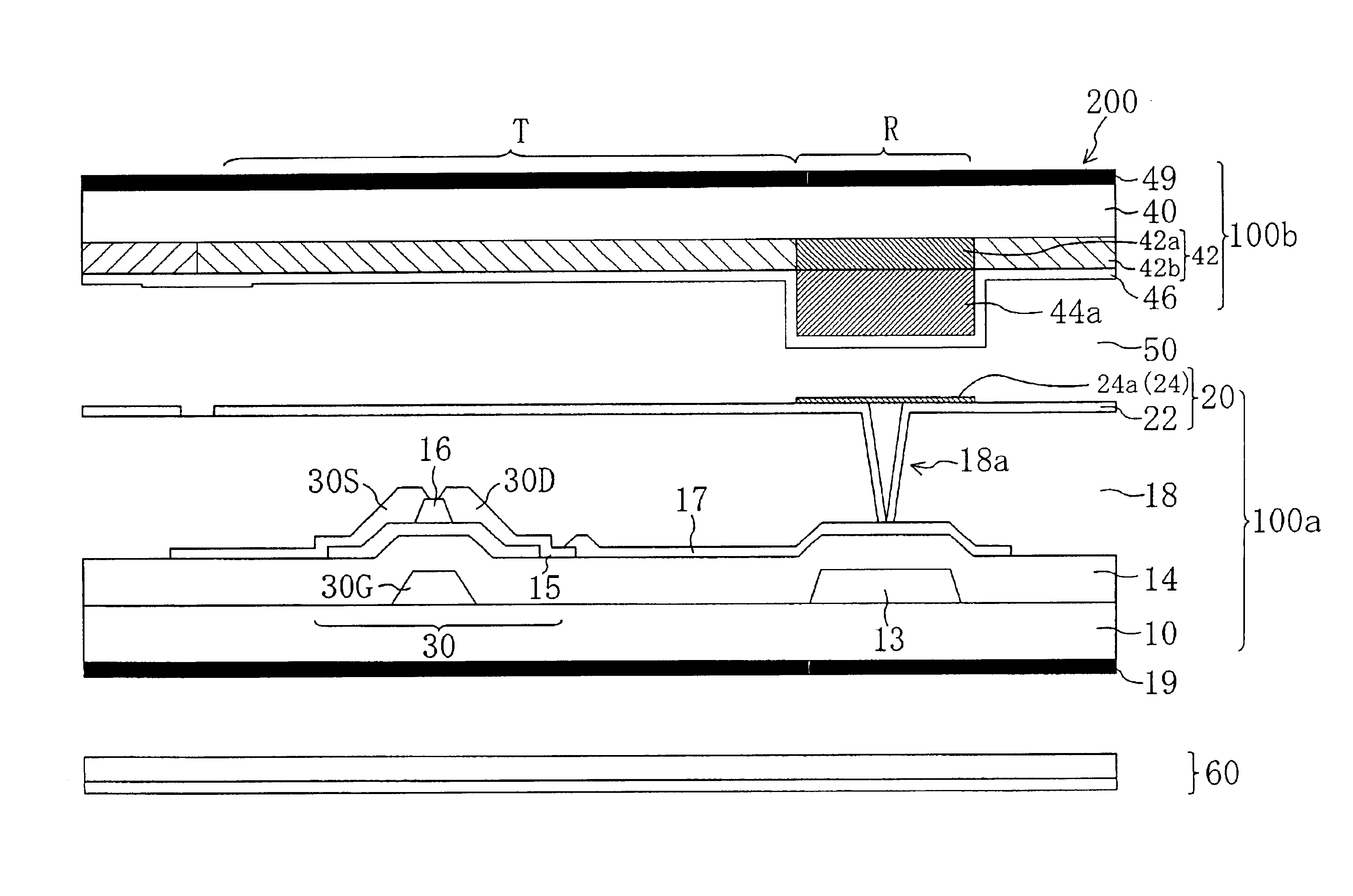
FIG. 7 schematically illustrates a liquid crystal display device 200 according to Embodiment 2 of the present invention. The liquid crystal display device 200 is different from the liquid crystal display device 100′ illustrated in FIG. 6 in that different materials are used for the color filter layer 42 in the reflection region R and the color filter layer 42 in the transmission region T.

A color filter layer 42b formed in the transmission region T is made of a material that has a relatively dark color (a material having a wide color reproduction range) so that the color filter layer 42b is suitable for displaying an image in the transmission mode. On the other hand, a color filter layer 42a formed in the reflection region R is made of a material that has a relatively light color and a high optical transmittance so that the color filter layer 42a is suitable for displaying an image in the reflection mode. In the present embodiment, the color filter layer 42a in the reflection region ...

embodiment 3

FIG. 8 schematically illustrates a liquid crystal display device 300 according to Embodiment 3 of the present invention. The liquid crystal display device 300 is different from the liquid crystal display device 200 illustrated in FIG. 7 in that the liquid crystal display device 300 does not include a transparent dielectric layer on the color filter layer 42, with the thickness of the color filter layer 42a in the reflection region R being larger than the thickness of the color filter layer 42b in the transmission region T, thereby providing a step on the surface of the color filter substrate 10b.

Herein, the color filter layer 42b in the transmission region T is formed with a thickness of 1 μm, and the color filter layer 42a in the reflection region R is formed with a thickness of 3.5 μm. Therefore, the height of the surface in the reflection region R is greater than that in the transmission region T by 2.5 μm, and the thickness of the liquid crystal layer 50 is 5.0 μm in the transm...


PUM

PropertyMeasurementUnit
widthaaaaaaaaaa
widthaaaaaaaaaa
thicknessaaaaaaaaaa

Abstract

A liquid crystal display device of the present invention includes: a first substrate; a second substrate; a liquid crystal layer provided between the first substrate and the second substrate; and a plurality of picture element regions for displaying an image. Each of the plurality of picture element regions includes a transmission region in which an image is displayed in a transmission mode by using light that is coming from the side of the first substrate, and a reflection region in which an image is displayed in a reflection mode by using light that is coming from the side of the second substrate. The height of a surface of the second substrate on the side closer to the liquid crystal layer in the reflection region is greater than that in the transmission region, while the height of a surface of the first substrate on the side closer to the liquid crystal layer in the reflection region is substantially equal to that in the transmission region.

Description

BACKGROUND OF THE INVENTION1. Field of the InventionThe present invention relates to a liquid crystal display device, and more particularly to a transmission / reflection combination type LCD capable of displaying an image in a transmission mode and in a reflection mode.2. Description of the Background ArtIn recent years, liquid crystal display devices, having desirable characteristics such as a small thickness and a small power consumption, have been widely used in various applications, including OA equipment such as word processors and personal computers, PDAs (personal digital assistance) such as electronic organizers, and camcorders with liquid crystal monitors.These liquid crystal display devices are generally classified into those of reflection type and those of transmission type. A liquid crystal display device is not self-luminous as is a CRT (cathode ray tube) or an EL (electroluminescence) device. A transmission type liquid crystal display device displays an image by using l...

Claims


Application Information

Patent Timeline
Patent Type & Authority Patents(United States)
IPC IPC(8): G02F1/1335G02F1/13G02F1/1333G02B5/20G02F1/1343G02F1/1368
CPCG02F1/133371G02F1/133514G02F1/133555G02F1/133553G02F2203/09G02F1/1335
Inventor FUJIMORI, KOHICHINARUTAKI, YOZOAKEBI, YASUNOBUKONISHI, IKUJI
Owner SHARP KK
Why Eureka
Try Eureka