Multi-service network switch

a network switch and multi-service technology, applied in the field of network switches, can solve the problems of network service providers facing extraordinary challenges, time-critical transactions, and inability to tolerate undue delay or disruption

Inactive Publication Date: 2005-02-01
ALCATEL LUCENT SAS
View PDF19 Cites 131 Cited by
  • Summary
  • Abstract
  • Description
  • Claims
  • Application Information

AI Technical Summary

Benefits of technology

The switch also provides tiered access of the Internet by defining quality of access (QoA) levels to each incoming connection request. The QoA levels allow the switch to prioritize the incoming connection requests when there is competition for resources. Preferably, a connection request with a higher QoA level is given a higher priority than a connection request with a lower QoA level.

Problems solved by technology

Today's network service providers face extraordinary challenges.
Many network-based business transactions are time-critical and typically cannot tolerate undue delay or disruption.
However, the problem with traditional access concentrators and high-end routers is that they are designed with a central CPU for centralized processing.
All data is passed through a centralized route forwarder / processor which increases processing overhead, causes bottlenecks, inhibits scalablility, and provides a single point of failure.
Essentially, the central processor cannot effectively process the increased amount of data traffic when new modules are added.
In addition to the challenge of growing traffic levels is the challenge of growing diversity of network technology.
Supporting each type of network technology in a traditional manner means that the ISPs typically add separate access servers, access routers, and / or stand alone LAN switches, generally resulting in an increase in cost and management complexities for the ISP.

Method used


Image

  • Multi-service network switch
  • Multi-service network switch
  • Multi-service network switch

Examples


Embodiment Construction

I. Multi-Service Network Switch System Architecture

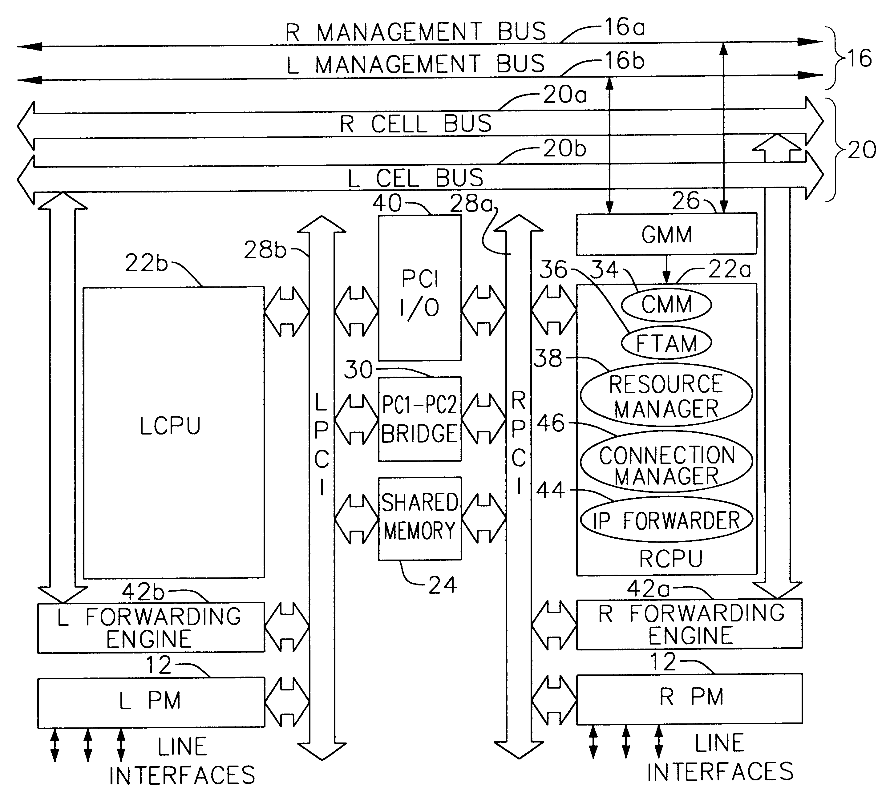
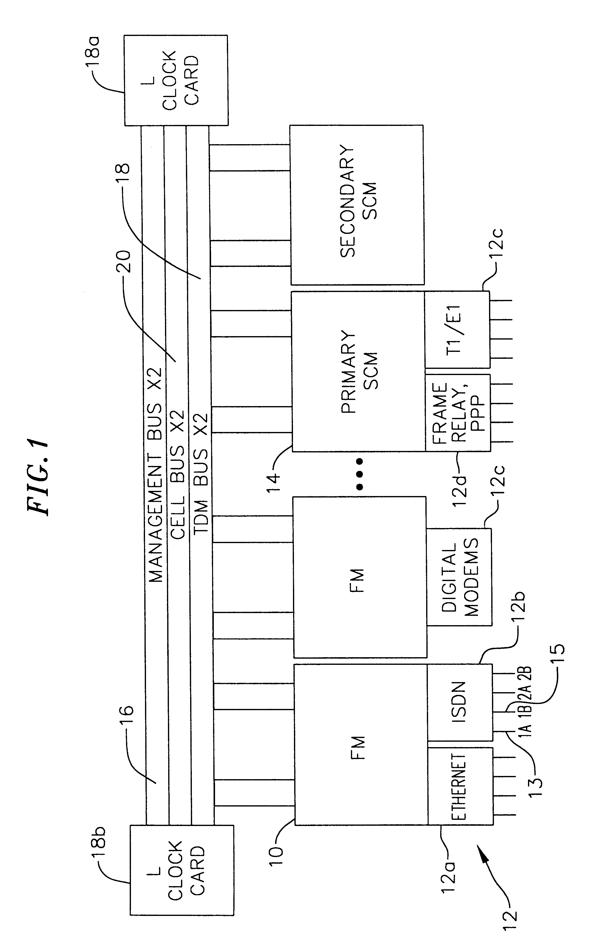
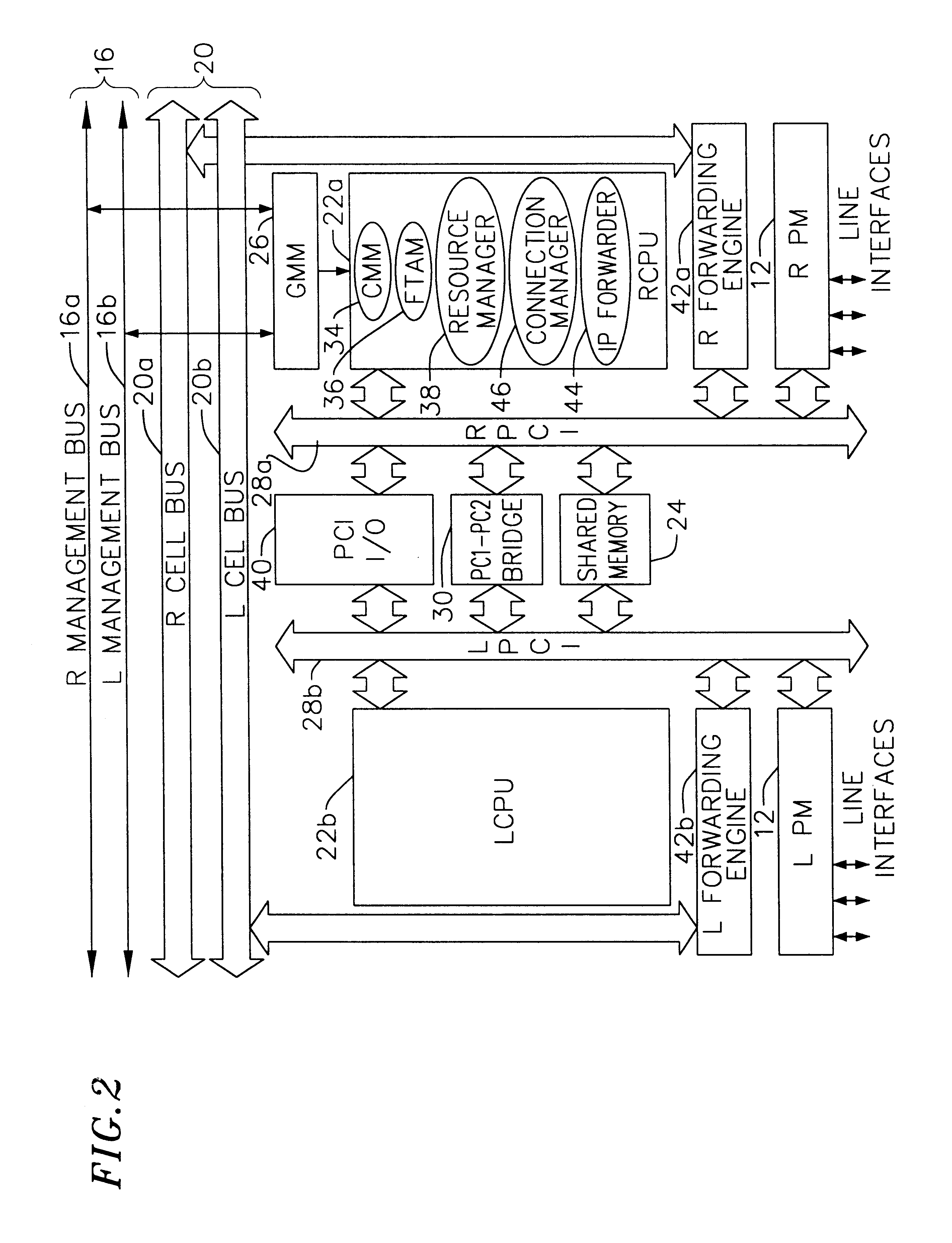
FIG. 1 is a schematic block diagram of a multi-service network switch (also referred to as the “chassis” or “system”) according to one embodiment of the invention. Each slot on the switch preferably accommodates a single interface module (a card), referred to as a forwarding module (FM) 10. Each FM 10 preferably includes the on-board intelligence, route forwarding, and route processing information for distributed packet forwarding, as is described in further detail below.

One type of FM, referred to as a system control module (SCM)14, hosts a route server and acts as the control point for network management. The SCM 14 also performs all the typical functions of an FM 10.

The switch includes at least two SCMs for fault tolerance, a primary SCM and a secondary SCM. The primary SCM is chosen at system startup, and announced to all the other FMs 10. The primary SCM preferably selects the secondary SCM as backup. If the primary SCM fails, ...


PUM


Abstract

A multi-service network switch capable of providing multiple network services from a single platform. The switch incorporates a distributed packet forwarding architecture where each of the various cards is capable of making independent forwarding decisions. The switch further allows for dynamic resource management for dynamically assigning modem and ISDN resources to an incoming call. The switch may also include fault management features to guard against single points of failure within the switch. The switch further allows the partitioning of the switch into multiple virtual routers where each virtual router has its own set of resources and a routing table. Each virtual router is further partitioned into virtual private networks for further controlling access to the network. The switch supports policy based routing where specific routing paths are selected based on a domain name, a telephone number, and the like. The switch also provides tiered access of the Internet by defining quality of access levels to each incoming connection request. The switch may further support an IP routing protocol and architecture in which the layer two protocols are independent of the physical interface they run on. Furthermore, the switch includes a generic forwarding interface software for hiding the details of transmitting and receiving packets over different interface types.

Description

FIELD OF THE INVENTIONThe present invention relates generally to network switches, and more particularly, to a multi-service network switch for providing multiple network services from a single platform.BACKGROUND OF THE INVENTIONToday's network service providers face extraordinary challenges. Traffic levels are rapidly increasing. Both consumers and corporations are demanding higher access rates and staying on the Internet longer while looking for predictable performance and stringent service-level guarantees. This puts direct demands on Internet Service Providers (ISPs) to provide larger capacity and higher speed at their point of presence (POP) locations, preferably without compromising performance.Just to maintain acceptable performance, service providers are adding support for more users, more traffic, and more transactions, preferably without introducing bottlenecks or compromising network availability. Many network-based business transactions are time-critical and typically c...

Claims


Application Information

Patent Timeline
Patent Type & Authority Patents(United States)
IPC IPC(8): H04L12/54H04L12/56
CPCH04L45/00H04L45/22H04L45/28H04L45/60H04L45/308H04L45/586H04L45/302
Inventor RAO, RAMAKRISHNAGHAHREMANI, CHARLIEYOUNG, DESMONDMURTHY, MANOTSENG, BENNAGARAJ, ASHWATHFARID, MEHDISCHUNK, RICHARD
Owner ALCATEL LUCENT SAS
Why Eureka
Try Eureka