Anti-fatigue mat

a technology of anti-fatigue and mats, applied in the field of mats, can solve the problems of fatigue, fatigue can still be experienced, and fatigue in the home or commercial kitchen, and achieve the effect of reducing user fatigue and enhancing adherence of the firs

Inactive Publication Date: 2005-02-08
MCMAHAN ROBERT L
View PDF8 Cites 41 Cited by
  • Summary
  • Abstract
  • Description
  • Claims
  • Application Information

AI Technical Summary

Benefits of technology

Another embodiment of the disclosed mat includes a resilient gel layer exhibiting first and second major opposed surfaces and a peripheral edge. The mat also includes a first flexible cover member situated on the first major opposed surface of the resilient gel layer. The first flexible cover member includes a first perimeter region. The mat further includes a second flexible cover member situated on the second major opposed surface of the resilient gel layer. The second flexible cover member includes a second perimeter region. The mat still further includes a support ring situated between the first and second perimeter regions adjacent the peripheral edge of the resilient gel layer to enhance adherence of the first and second flexible cover members together around the resilient gel layer thus enclosed.
A principal advantage of the embodiment disclosed herein is that user fatigue is significantly reduced.

Problems solved by technology

However, fatigue can still result when a person stands on a mat for an extended period of time.
Persons who work standing up most of the day, such as cashiers, assembly line operators, people in home or commercial kitchens and many others still experience fatigue after standing on a conventional mat for long periods of time.
Unfortunately however, foam mats have the disadvantage of becoming brittle over time.
Also, conventional foam mats collect moisture over time.
These undesirable characteristics result in foam mats becoming unsuitable for use as they become older.

Method used


Image

  • Anti-fatigue mat
  • Anti-fatigue mat
  • Anti-fatigue mat

Examples


Embodiment Construction

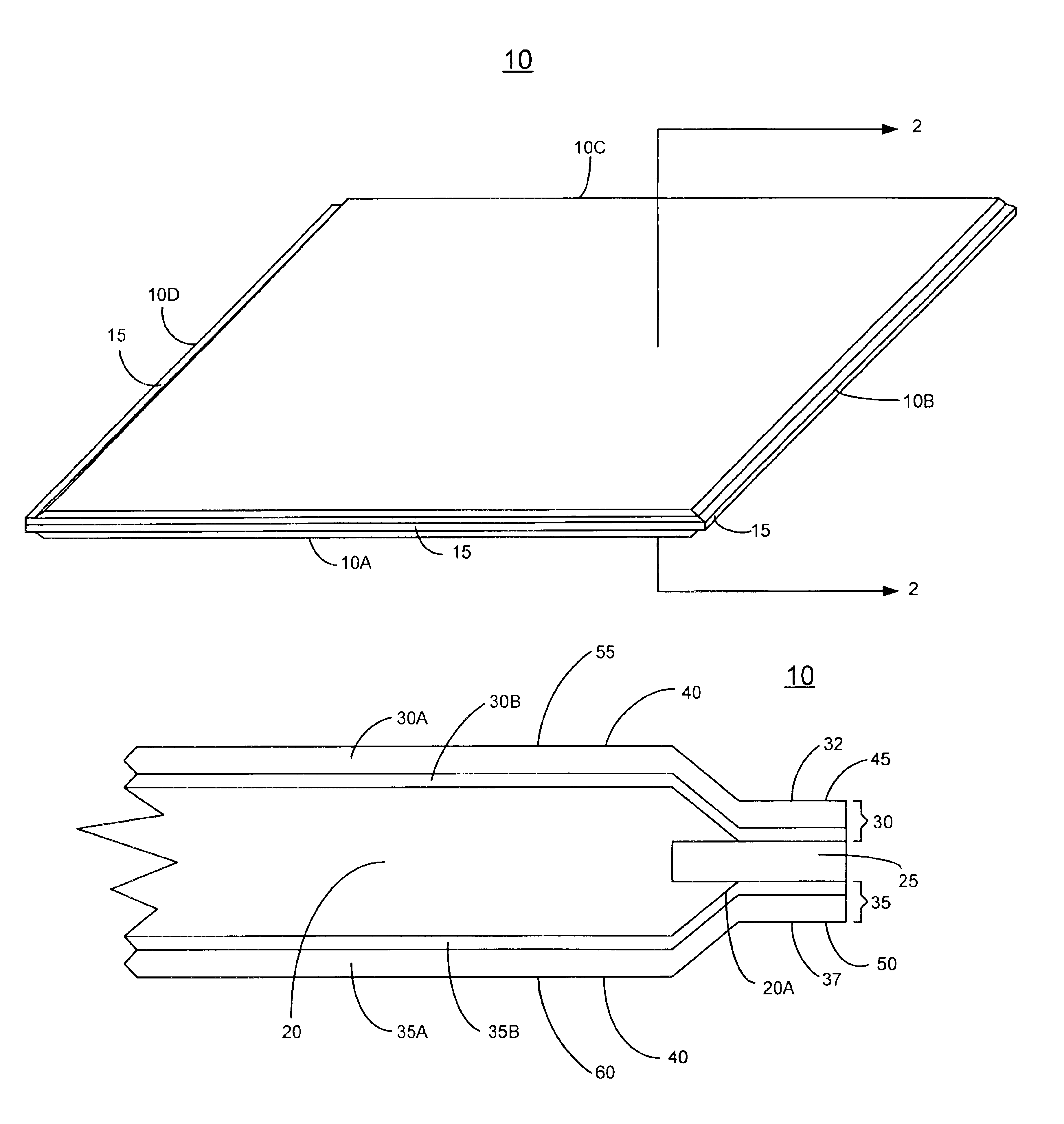
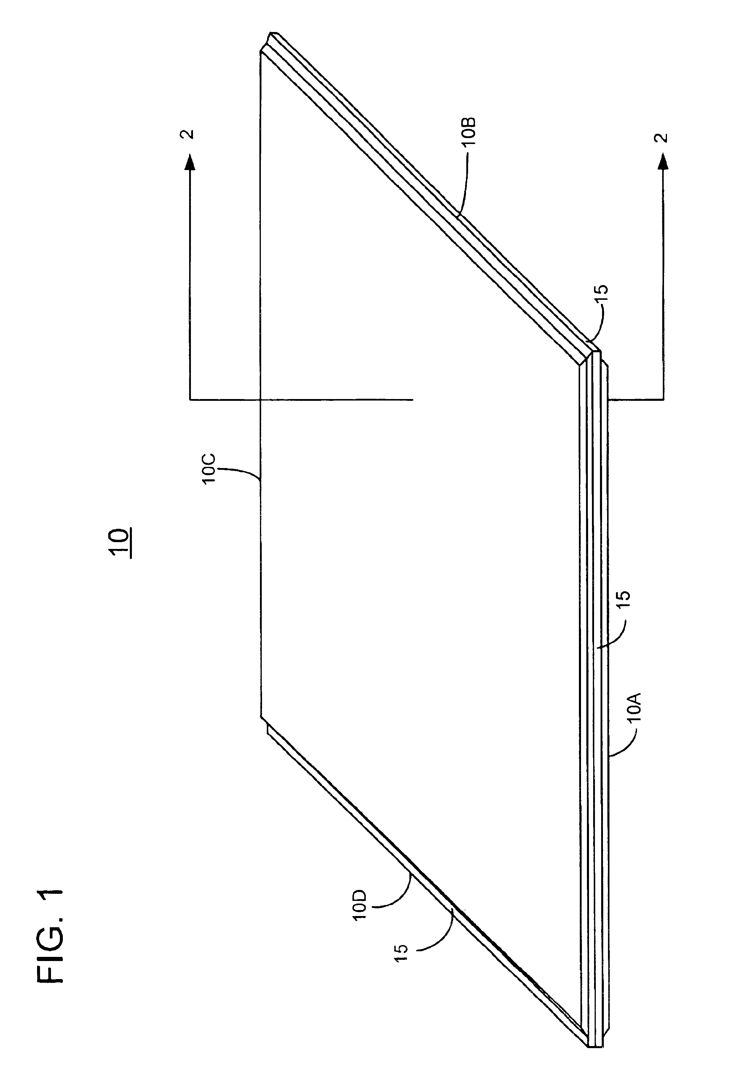
FIG. 1 shows one embodiment of the disclosed anti-fatigue mat as mat 10. Mat 10 includes an edge surface 15 which extends around the perimeter formed by sides 10A, 10B, 10C and 10D. In this particular implementation, mat 10 is rectangular. However, the disclosed mat can readily be adapted to other geometries such as square, circular and elliptical, for example.

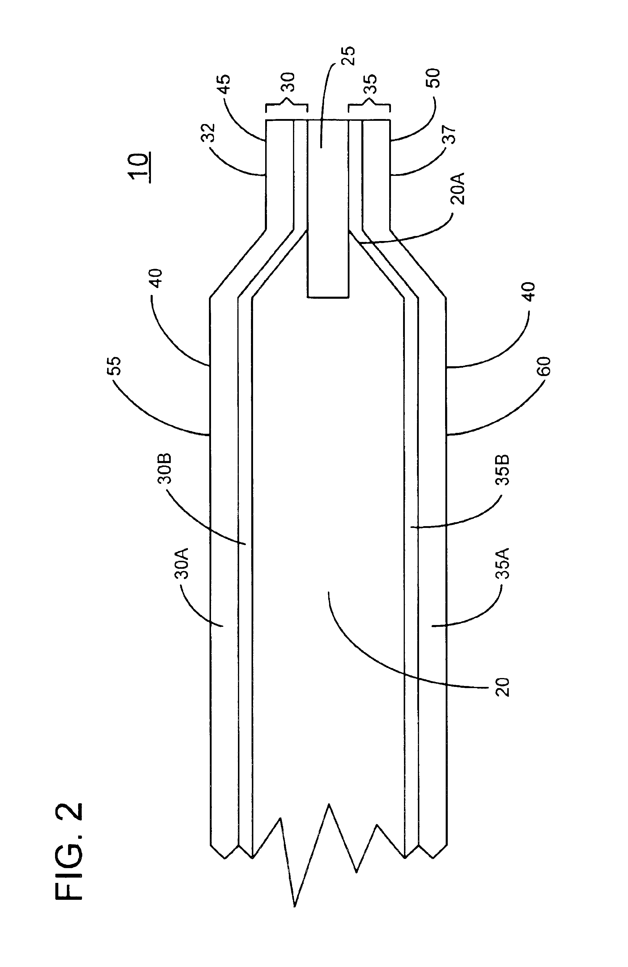
To more clearly show the inner details of mat 10, FIG. 2 provides a cross section of the mat taken along section line 2—2 of FIG. 1. As seen in FIG. 2, mat 10 includes an inner layer 20 fabricated of resilient material, for example a viscoelastic polymer material such as a polyurethane-based gel or a silicon-based gel. A support ring 25 made of a stiff material is located adjacent peripheral edge 20A of resilient inner layer 20 as shown. Support ring 25 extends around the perimeter of mat 10 and stiffens the mat at its periphery as will be discussed in more detail later.

A cover member 30 is situated atop resilient inner layer ...


PUM

PropertyMeasurementUnit
pressureaaaaaaaaaa
pressureaaaaaaaaaa
flexibleaaaaaaaaaa

Abstract

A resilient mat is disclosed which provides cushioning and comfort to users standing thereon or otherwise contacting the mat. The mat includes a resilient gel inner layer surrounded by a support ring to which an upper cover member and a lower cover member are attached. The support ring exhibits stiffness greater than the stiffness of the upper and lower cover members so that adherence of the upper and lower cover members to the support ring is enhanced even after prolonged use. The upper and lower cover members can exhibit the same or different colors in particular embodiments. The upper and lower cover members also can exhibit anti-slip properties in selected embodiments.

Description

BACKGROUNDThe disclosures herein relate generally to mats and more particularly to resilient floor mats for reducing user fatigue.Floor mats have been used for years to provide a cushion for the person standing on the mat. However, fatigue can still result when a person stands on a mat for an extended period of time. Persons who work standing up most of the day, such as cashiers, assembly line operators, people in home or commercial kitchens and many others still experience fatigue after standing on a conventional mat for long periods of time. Often floor mats are provided with non-slip surfaces to lessen slippage and to thus promote safety.Mats of resilient foam are known to reduce user fatigue. Unfortunately however, foam mats have the disadvantage of becoming brittle over time. Conventional foam mats lose their properties as air cells in the mat compress. Also, conventional foam mats collect moisture over time. This condition can promote the growth of bacteria and fungus. These u...

Claims


Application Information

Patent Timeline
Patent Type & Authority Patents(United States)
IPC IPC(8): A47G27/00A47G27/02
CPCA47G27/0231Y10T428/24033Y10T428/24785Y10T428/239Y10T428/233Y10T428/24793
Inventor MCMAHAN, ROBERT L.
Owner MCMAHAN ROBERT L
Why Eureka
Try Eureka