Fluid leakage detection apparatus and fluid leakage detection method

a leakage detection and fluid technology, applied in the field of fluid leakage detection apparatus and method, to achieve the effect of detection of leakag

Active Publication Date: 2005-02-08
TOYOTA JIDOSHA KK
View PDF21 Cites 40 Cited by
  • Summary
  • Abstract
  • Description
  • Claims
  • Application Information

AI Technical Summary

Benefits of technology

It is an object of the invention to provide an apparatus and method that detects leakage of the

Problems solved by technology

There may be the case that the fluid leaks firm a crac

Method used


Image

  • Fluid leakage detection apparatus and fluid leakage detection method
  • Fluid leakage detection apparatus and fluid leakage detection method
  • Fluid leakage detection apparatus and fluid leakage detection method

Examples


modified example 1

C: Modified Example 1

FIG. 5 is a flowchart resenting a control routine for leakage detection according to a modified example of the invention. FIG. 6 is a timing chart representing the control routine for leakage detection according to the modified example.

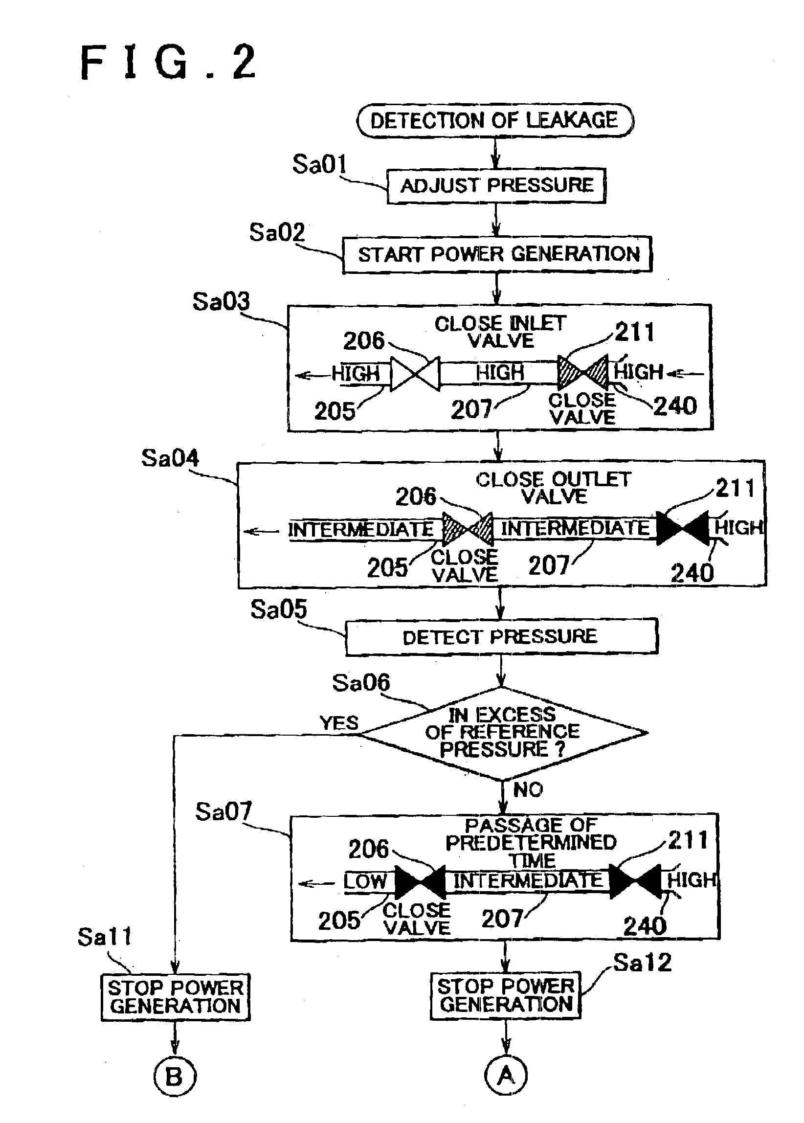
Steps Sa01, Sa02 of the flowchart shown in FIG. 5 are the same as those shown in the flowchart of FIG. 2. Upon drop in the pressure within the pipe 223, the power generation system 120 starts its power generating operation.

In step Sd03, the adjustment section 111 closes the outlet valve 206 at a timing Se2. This may decrease the pressure within the pipe 205 while keeping the pressure within the pipe 207 upstream of the outlet valve 206 high.

In step Sd04, the inlet valve 211 is closed at a timing Se3. In step Sd05, the outlet valve 206 is opened at a timing Se4. Then the pressure within the pipe 207 starts decreasing. When the pressure within the pipe 207 decreases to reach a predetermined pressure, the outlet valve 206 is closed i...

modified example 2

D: Modified Example 2

In step Sb33 of the flowchart shown in FIG. 3, the leakage in the outlet valve 206 is determined. However, the leakage in the pipe 207 caused by its crack portion may be determined in step Sb33 of the flowchart shown in FIG. 3. This makes it possible to detect the leakage both in the inlet valve 211 and the pipe 207 at the same time quickly. The leakage in the pipe 207 may only be determined in step Sb33. Alternatively the leakage in the pipe 207 and the leakage in the outlet valve 206 may be determined at the same time in step Sb33.

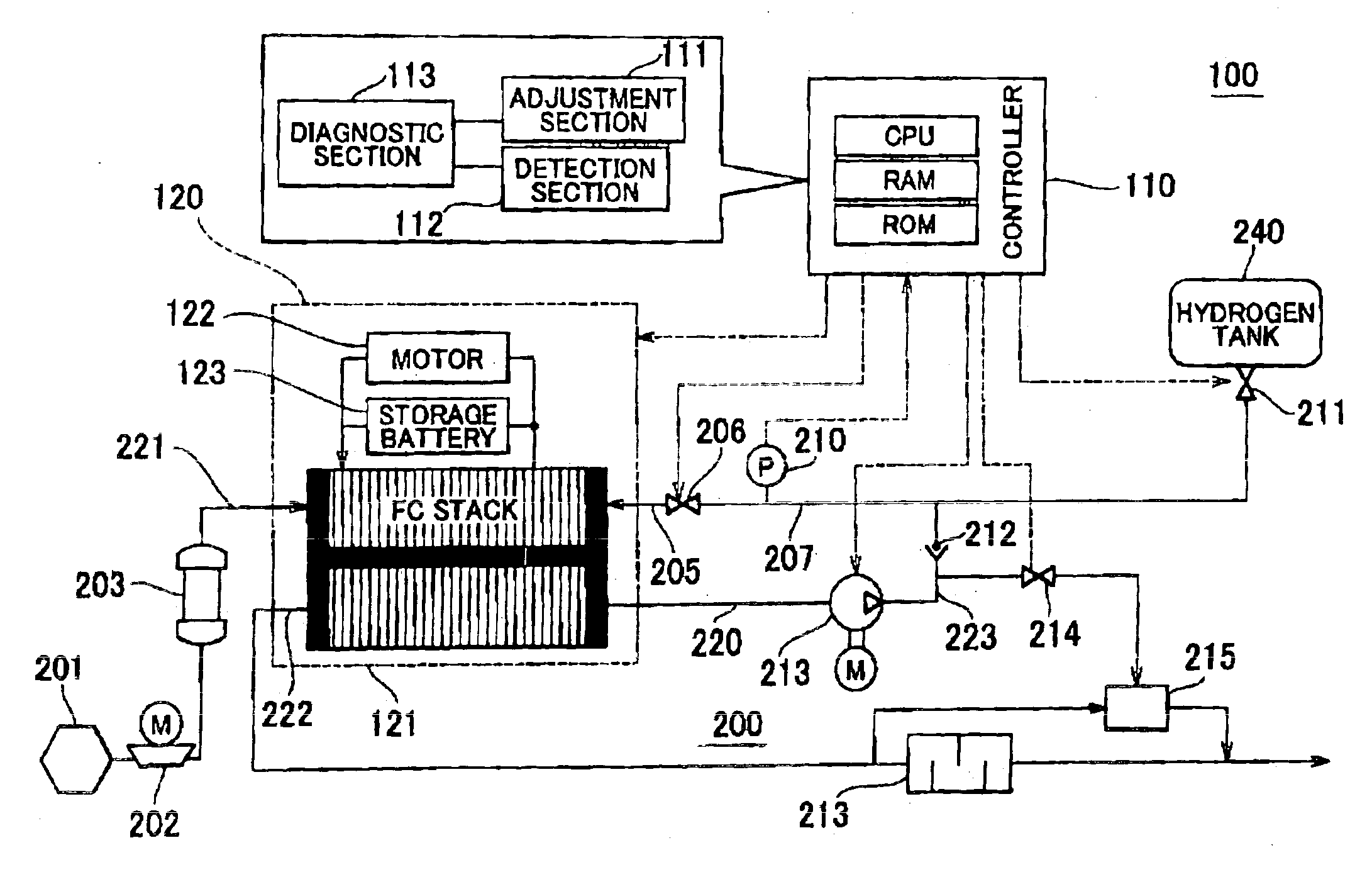
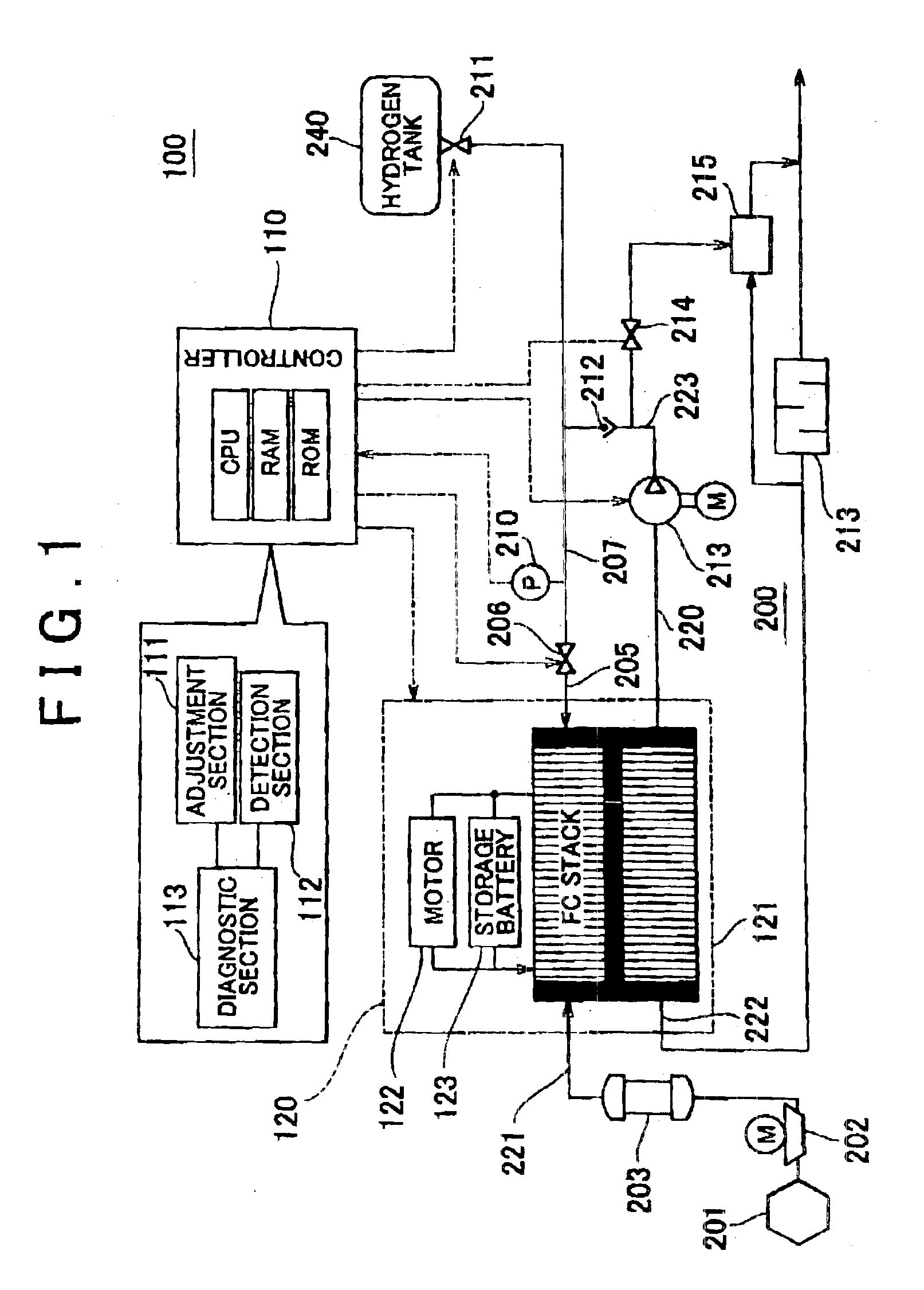
FIG. 7 is a schematic view of a fuel cell system 100a including a regulator 900 provided on an intermediate portion of the pipe 207. FIG. 7 shows only the system for supplying hydrogen to the FC stack 121, and other elements of the structure are the same as those shown in the embodiment shown in FIG. 1. The regulator 900 serves to operate to uniformize the pressure between the regulator 900 and the outlet valve 206.

It is preferable t...


PUM


Abstract

In a fluid leakage detection apparatus, hydrogen is supplied from a hydrogen tank to an FC stack of a fuel cell via first and second pipes. An inlet valve is provided between the hydrogen tank and the first pipe, and an outlet valve is provided between the first pipe and the second pipe. A controller serves to control valve opening a valve closing operation of the inlet and outlet valves, respectively. Those valves are closed in a state where the pressure within the hydrogen tank is made lower than the pressure within the first pipe, and the pressure within the second pipe is made lower than the pressure within the first pipe by operating those valves. Thereafter, the increase or decrease in the pressure within the first pipe is detected by a pressure gauge such that the leakage in the inlet valve or the outlet valve is determined. This makes it possible to detect the leakage both in the inlet valve and the outlet valve at the same time.

Description

INCORPORATION BY REFERENCEThe disclosure of Japanese Patent Application No.2002-338658 filed on Nov. 22, 2002, including the specification, drawings and abstract is incorporated herein by reference in its entirety.BACKGROUND OF THE INVENTION1. Field of the InventionThe invention relates to a fluid leakage detection apparatus and method for detecting a fluid leakage in a system including a fluid passage that allows the fluid to flow therethrough, and a plurality of valves provided on intermediate portions of the fluid passage.2. Description of Related ArtGenerally a system that includes a piping and a plurality of valves provided on intermediate portions thereof has been known as being used for a fluid supply. A fuel cell system, for example, employs a system for supplying hydrogen and oxygen to the fuel cell. The flow of the fluid can be interrupted by closing valves provided on intermediate portions of the piping.The aforementioned system employs a detector that detects leakage of ...

Claims


Application Information

Patent Timeline
IPC IPC(8): G01M3/26G01M3/04G01M3/32G01M3/28H01M8/04F23N5/24
CPCF23N5/242G01M3/3236F23N2031/18F23N2025/04F23N2225/04F23N2231/18
Inventor MIURA, SHIMPEIKURITA, KENJIYOSHIDA, NAOHIROUMAYAHARA, KENJI
Owner TOYOTA JIDOSHA KK
Why Eureka
Try Eureka