Pressurized package comprising a pressure control device

a control device and pressure control technology, applied in the direction of functional valve types, liquid dispensing, containers, etc., can solve the problems of inability to accurately operate during, the diaphragm has a certain rigidity and limited freedom of movement, and the spring provides rather an inaccurate reference force on the diaphragm, so as to avoid friction

Inactive Publication Date:
View PDF19 Cites 34 Cited by
  • Summary
  • Abstract
  • Description
  • Claims
  • Application Information

AI Technical Summary

Benefits of technology

According to a preferred embodiment, it holds that the pressure control device comprises at least one sealing element, such as a rubber ring and the controllable seal comprises a bar-shaped element connected to the plunger outside the space enclosed by the chamber and the plunger, while in the first position, the bar-shaped element and the sealing element release the fluid flow path and in the second position, the bar-shaped element an

Problems solved by technology

A problem of the known device is that it does not operate accurately during pressure control.
Indeed, the diaphragm has a certain rigidity and a limited freedom of movement.
Further, the spring provides rather an inaccurate refer

Method used


Image

  • Pressurized package comprising a pressure control device
  • Pressurized package comprising a pressure control device
  • Pressurized package comprising a pressure control device

Examples


Embodiment Construction

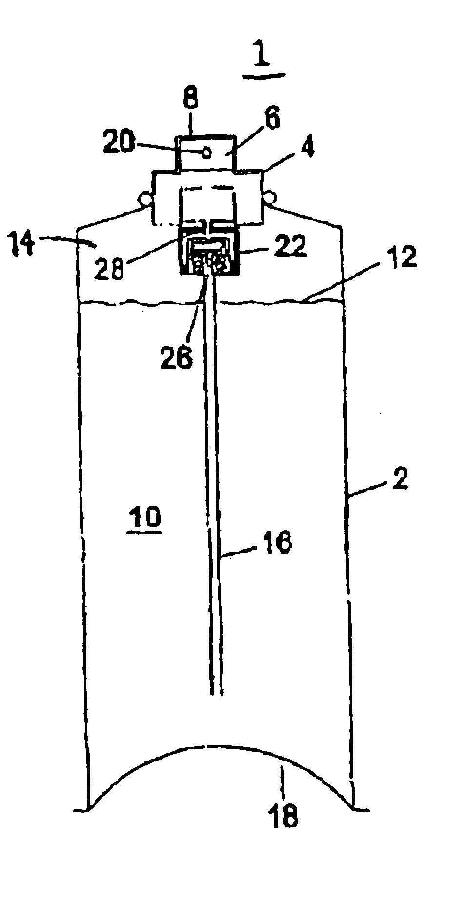
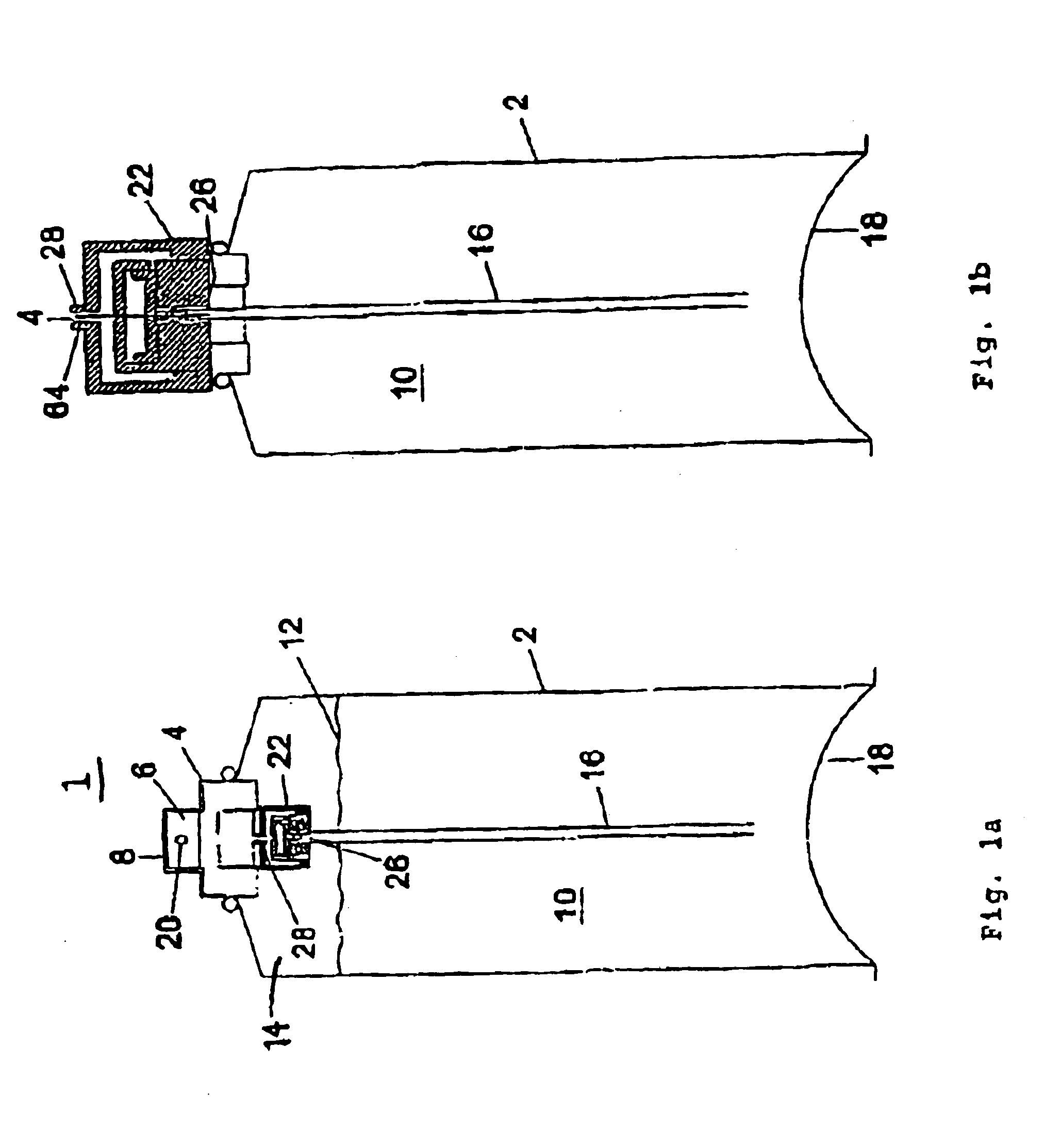
In FIG. 1a, reference numeral 1 designates an assembly according to the invention. The assembly 1 comprises a package 2 which, in this example, consists of a can known per se, such as the can of an aerosol can. The assembly further comprises an outlet 4 located on top of the package 2.

The outlet 4 is located on the outer side of the package. In this example, the outlet 4 comprises a push button, known per se, located on top of an aerosol can. Accordingly, outside the package, the outlet 4 comprises a shutoff valve 6, known per se, for opening and closing the outlet. The shut-off valve 6 is opened when the push button 8 of the outlet 4 is pressed upon. An inner space 10 of the package 2 is partially filled with a fluid 12, in this example consisting of a liquid. The fluid is the product which is to be dispensed. The inner space 10 can, for instance, be filled with the liquid 12 for 90%. In the remaining space of the inner space 10, an inert gas 14 is present, such as, for instance, n...


PUM


Abstract

A pressurized package assembly includes a package having an least one outlet. In use, an inner space of the package is filled with a fluid that is dispensed via the outlet. In the inner space of the package, there prevails a pressure which can vary. The assembly also includes a pressure control device for feeding to the outlet, via the pressure control device, the fluid at a predetermined constant pressure.

Description

FIELD OF THE INVENTIONThe present invention is directed to pressurized assemblies for dispensing a fluid.BACKGROUND OF THE INVENTIONThe prior art includes an assembly comprising a package and at least one outlet wherein, in use, an inner space of the package is filled with fluid to be dispensed, wherein in the inner space of the package there prevails a pressure for enabling dispensing the fluid via the outlet, the assembly further comprising a pressure control device connected to the outlet adjacent the outlet, for feeding the fluid to the outlet via the pressure control device at a predetermined constant pressure which is independent of and less than the pressure prevailing in the inner space of the package, the pressure control device comprising a housing provided with an inflow opening, an outflow opening and a fluid flow path extending in the housing between the inflow opening and the outflow opening, the inflow opening being in fluid connection with the inner space of the pack...

Claims


Application Information

Patent Timeline
IPC IPC(8): B65D83/14G05D16/10G05D16/04B01J4/00B65D83/46B05B9/04B67D1/04F16K17/04F16L55/00
CPCB65D83/44G05D16/10Y10S137/906G05D16/106Y10T137/0396Y10T137/7825
Inventor VAN'T HOFF, JAAP HERMAN
Why Eureka
Try Eureka