High-pressure cleaning spray nozzle

a high-pressure, spray nozzle technology, applied in the direction of pliable tubular containers, combustion types, lighting and heating apparatus, etc., can solve the problems of reducing the impact force, inadequate and/or uneven cleaning of the surface, and the difficulty of directing a concentrated solid liquid stream at relatively high liquid pressure, so as to reduce the turbulence of liquid and reduce the impact force , the effect of uniform surface cleaning

Inactive Publication Date: 2005-02-08
SPRAYING SYST
View PDF13 Cites 25 Cited by
  • Summary
  • Abstract
  • Description
  • Claims
  • Application Information

AI Technical Summary

Benefits of technology

A further object is to provide a spray nozzle of the above kind in which the discharging liquid flow stream is effective for uniform surface cleaning.
Still another object is to provide a spray nozzle of the foregoing type which has an internal fluid passageway design which reduces liquid turbulence of the liquid at high pressures and directs a concentrated solid liquid flow stream for greater impact.
Yet another object is to provide a spray nozzle of such type which is adapted for economical manufacture.

Problems solved by technology

However, as the liquid pressure increases, increased turbulence within the spray nozzle and the discharging flow stream can disrupt and break up the concentration of the flow stream, thereby reducing its impact force.
The resulting non-uniformity of the broken up stream further can result in inadequate and / or uneven cleaning of a surface.
Heretofore it has been difficult to direct a concentrated solid liquid stream at relatively high liquid pressures.

Method used


Image

  • High-pressure cleaning spray nozzle
  • High-pressure cleaning spray nozzle
  • High-pressure cleaning spray nozzle

Examples


Embodiment Construction

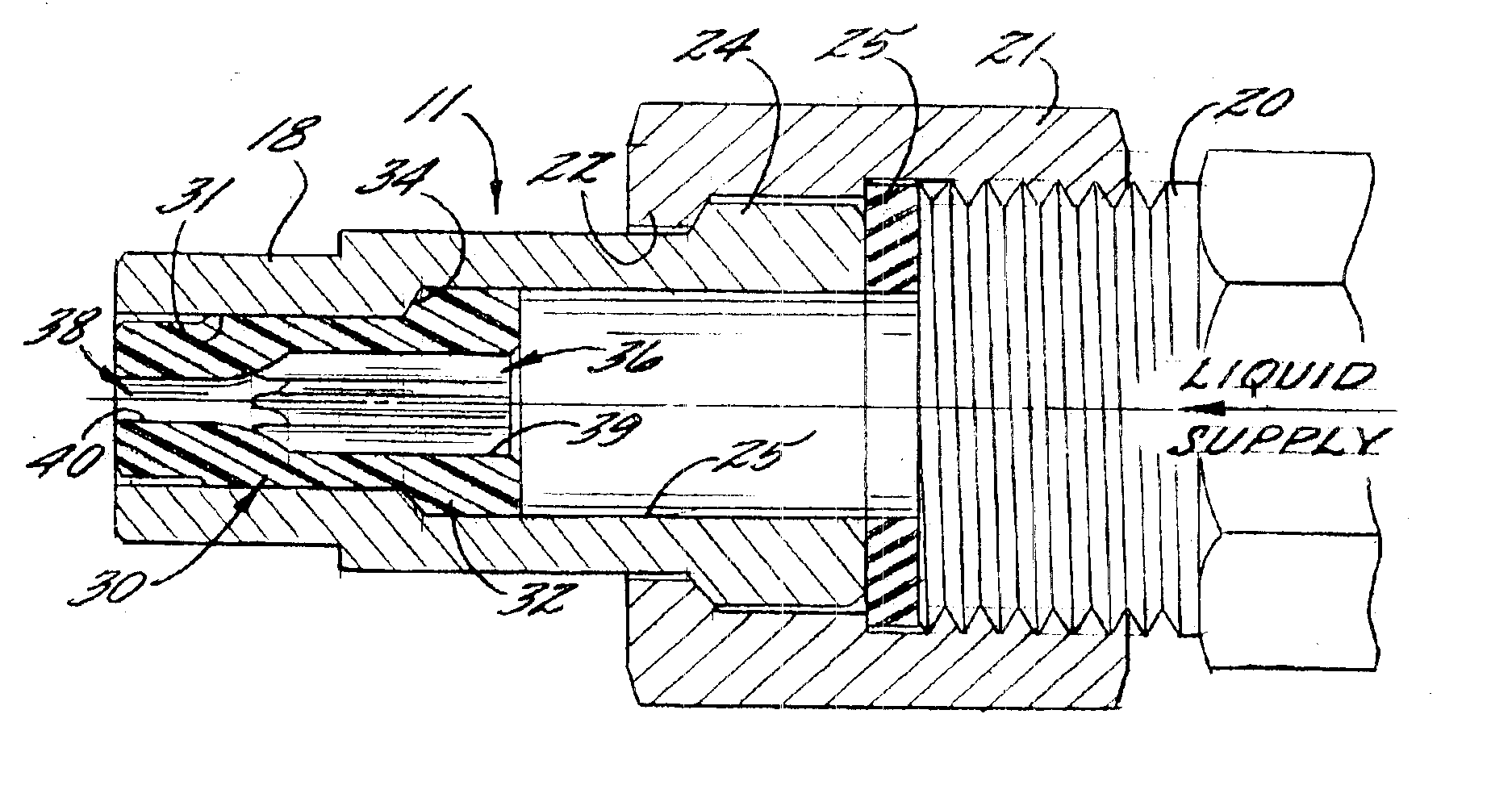
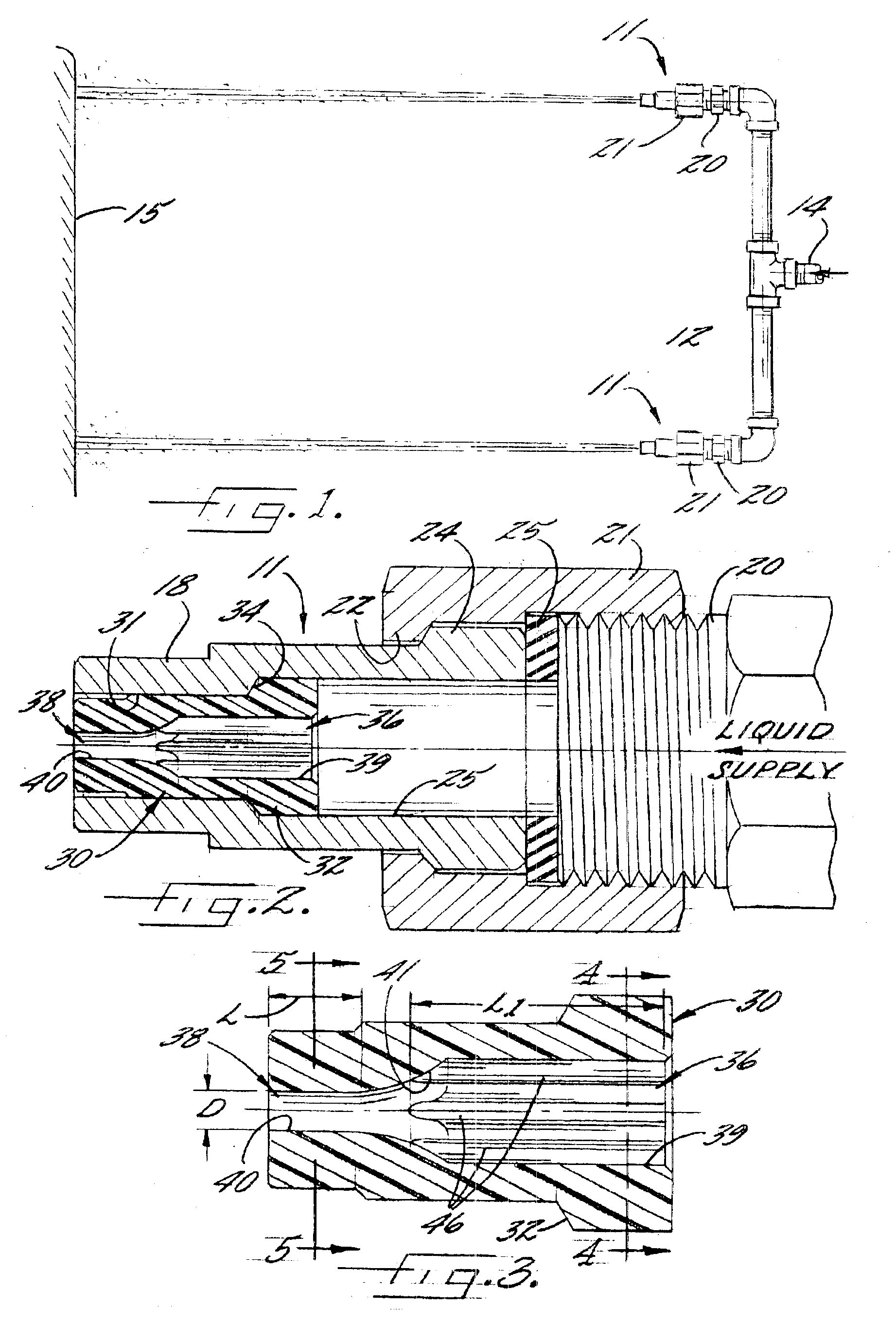
Referring now more particularly to FIGS. 1-5 of the drawings, there is shown an illustrative spray apparatus 10 having a plurality of spray nozzles 11 in accordance with the present invention. Spray nozzles 11 in this case are mounted in parallel relation to each other at opposite ends of a header pipe 12, which in turn is coupled through a central supply pipe 14 to a pressurized liquid supply, such as water or other suitable cleaning solutions or fluids. The spray nozzles 11 direct respective high-pressure liquid streams against a surface 15 to be cleaned. Since each of the spray nozzles 1 is identical in construction, only one need to be described in detail.

The illustrated spray nozzle 11 has a nozzle body 18, preferably constructed in one piece of metal or other suitable material for necessary strength. The nozzle body 18 includes an upstream end, which may be connected to a forwardly extended externally threaded end 20 of the header 12 by means of a threaded retaining ring 21. T...


PUM


Abstract

A high-pressure liquid spray nozzle having an elongate nozzle body having a longitudinally extending liquid flow passage, which in the illustrated embodiment, is defined in part by a plastic liquid throttling and stabilizing insert. The insert has a liquid flow passage which includes an upstream entry section, a smaller diameter downstream approach section, and an inwardly converging throat section between the upstream and downstream sections. The upstream passageway section has a scalloped cross-sectional configuration which define a plurality of longitudinally extending flutes effective for stabilizing and minimizing turbulence in the high pressure liquid flow stream directed through the nozzle such that a more concentrated, solid liquid flow stream is discharged from the nozzle with increased velocity and surface impact force for enhanced cleaning.

Description

FIELD OF THE INVENTIONThe present invention relates generally to spray nozzles, and more particularly, to spray nozzles for high pressure cleaning applications.BACKGROUND OF THE INVENTIONSpray nozzles for high pressure cleaning applications direct a high velocity liquid stream against a surface to be cleaned. The liquid stream forcefully impinges against the surface in order to remove dirt or other particles thereon. Such nozzles, for example, are commonly used in pressure washers, car washes, and other cleaning applications. The trend has been to use increasingly higher liquid pressures in order to achieve greater impact forces. However, as the liquid pressure increases, increased turbulence within the spray nozzle and the discharging flow stream can disrupt and break up the concentration of the flow stream, thereby reducing its impact force. The resulting non-uniformity of the broken up stream further can result in inadequate and / or uneven cleaning of a surface. Heretofore it has ...

Claims


Application Information

Patent Timeline
Patent Type & Authority Patents(United States)
IPC IPC(8): B05B1/34B05B1/02B05B1/04
CPCB05B1/34B05B1/042B05B1/02B05B1/3402
Inventor FERRAZZA, GERALD P.VOCK, TIMOTHY M.
Owner SPRAYING SYST
Why Eureka
Try Eureka