Fiber optic fabric with opaque coating for directional light emission

a fiber optic fabric and opaque coating technology, applied in the field of fiber optic materials, can solve the problems of increasing light leakage, inability to allow both lit and unlit areas along the fiber, and inefficient directional lighting

Inactive Publication Date: 2005-02-08
THE BOEING CO
View PDF12 Cites 68 Cited by
  • Summary
  • Abstract
  • Description
  • Claims
  • Application Information

AI Technical Summary

Problems solved by technology

This leakage may be due to light rays exceeding the critical angle for internal reflection.
Bends in the fiber and scratches on the fiber surface may increase the light leakage at those points.
Unfortunately, these fibers do not allow for both lit and unlit areas along the fiber.
Additionally, they are inefficient at directional lighting.
Unfortunately, it may not be desirable for light to be emitted from the entire surface of the ribbon.
Also, the hot stamping may structurally weaken the fibers.
Although, these fibers may allow for some areas along the fiber to be lit and others unlit, the bending may cause fiber breakage.
Additionally, there may be light leakage from the unbent sections of the fiber.
Because light is emitted from these fibers in all directions at the bends, directional control of the light emission is inefficient.
Also, the use of luminaries may have an adverse effect on aerodynamics, such as when the luminaires are attached to the outer mold line (OML) of an aircraft.
Notched fibers may laterally emit light, but the notches may weaken the fibers.
Optical fibers may not be totally efficient at transmitting light and some light may leak into the cladding and produce a glow along the length of the fiber.
Unfortunately, concealment of the optical fibers when unlit may be desired in some applications.
Additionally, a fabric having uniform light emission may not be efficient when directional light emission is desired.

Method used


Image

  • Fiber optic fabric with opaque coating for directional light emission
  • Fiber optic fabric with opaque coating for directional light emission
  • Fiber optic fabric with opaque coating for directional light emission

Examples


example 1

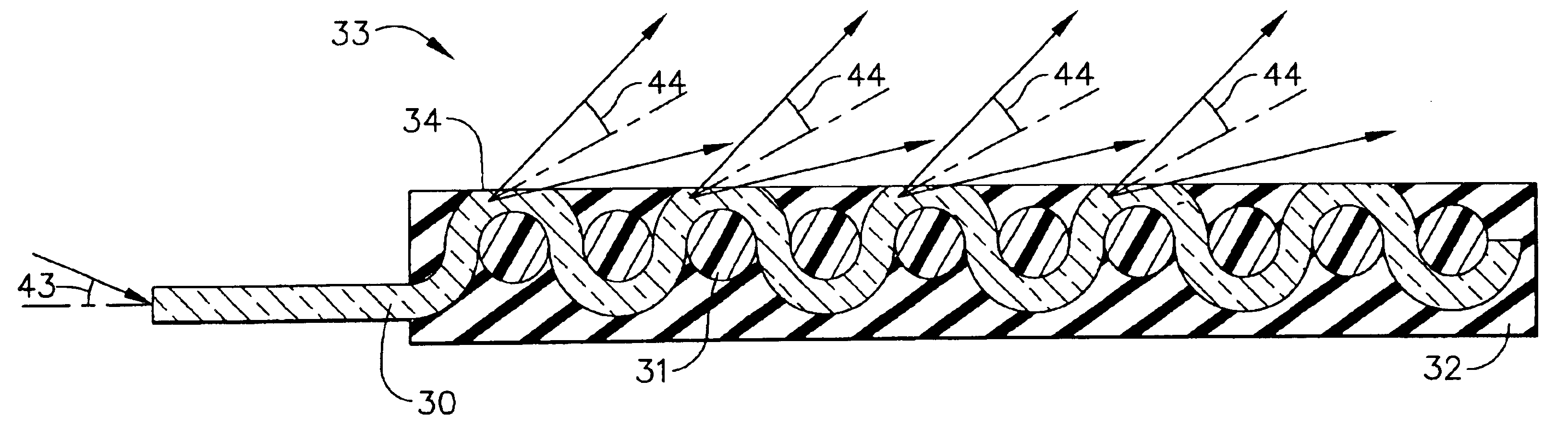
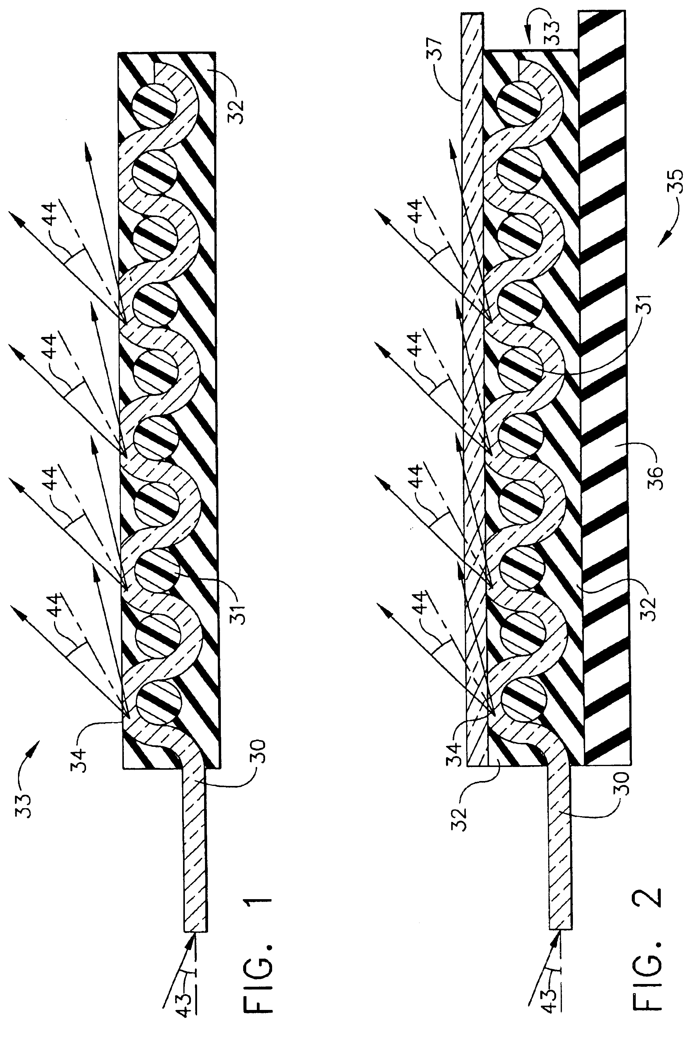
A fiber optic fabric was produced according to an embodiment of the present invention. A sample of Fibertex™ fabric was purchased from Lumitex, Inc., Strongsville, Ohio. A coating 32 comprised of black epoxy was applied to the fabric by painting. The coated fabric was then sanded. The sanding removed the coating 32 and the fiber cladding at the high points of the weave, producing the openings 34.

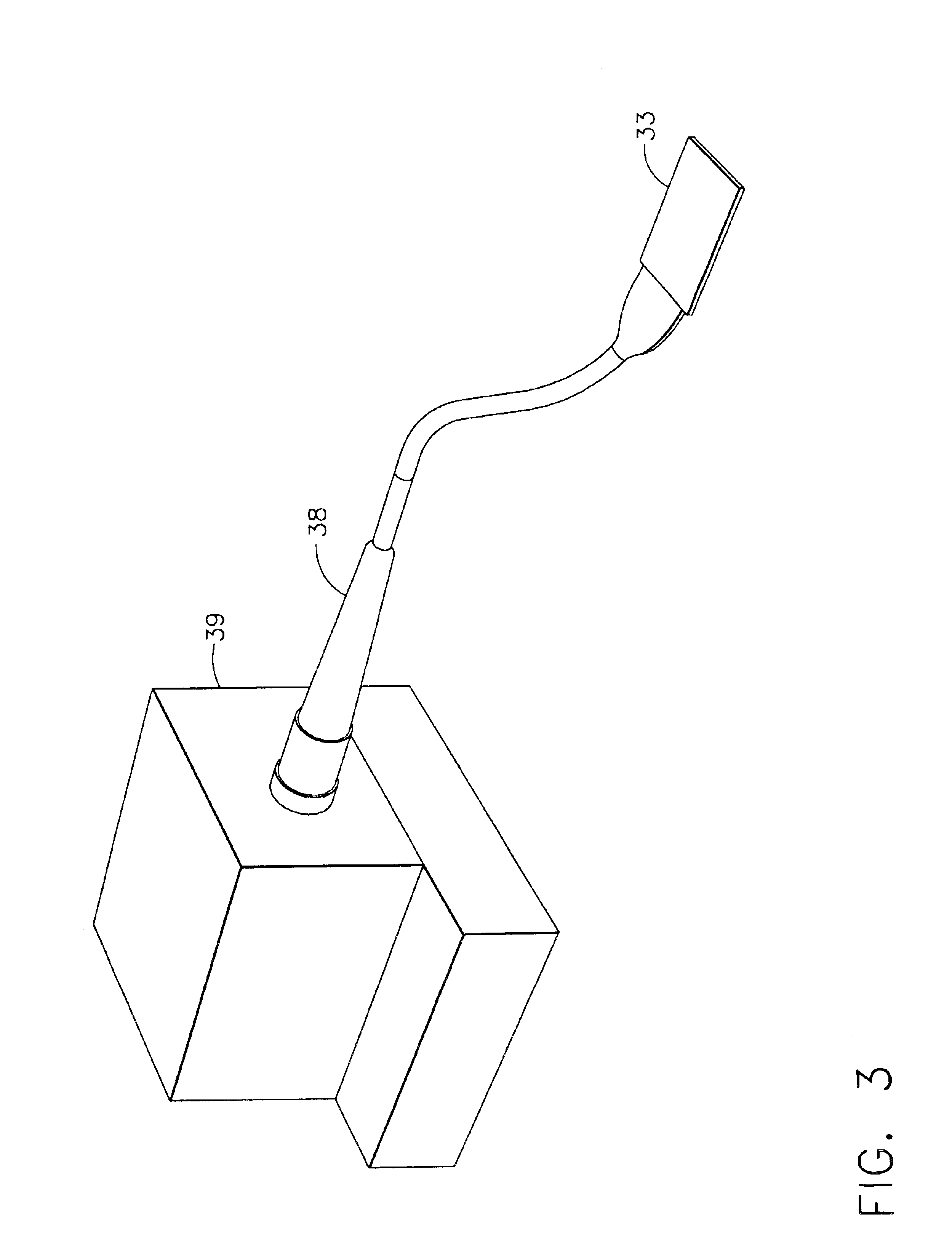
A system for illuminating the fabric is shown in FIG. 3. As can be seen, a glass rod 38 was then attached to the fiber optic fabric 33, and a light engine 39 was connected to the glass rod 38. The glass rod 38, which is known in the art, may be any fiber optic light guide with suitable couplings. The light engine 39, which is known in the art, may be any source of illumination. The fabric was then photographed at various elevations from the plane of the fabric to show the angular intensity distribution. FIGS. 4 through 9 are photographs of the fabric as seen from elevations of 10°, 26°, 42°,...


PUM

PropertyMeasurementUnit
exit angleaaaaaaaaaa
angleaaaaaaaaaa
acceptance angleaaaaaaaaaa

Abstract

A fiber optic fabric includes woven optical fibers, an opaque coating on the fibers and openings on the high points of the weave. The opaque coating prevents light leakage from the fibers and the openings allow light to be emitted from the fabric in a directed manner. The fabric is capable of emitting light at an angle relative to the surface of the fabric such that the light is not visible from every viewpoint.

Description

BACKGROUND OF THE INVENTIONThe present invention generally relates to fiber optic materials and methods for producing same. More specifically, this invention relates to fiber optic fabric incorporating woven optical fibers.Optical fibers have been used in many devices and materials. These fibers may comprise a core and a cladding material. The core may comprise glass or plastic resin. The cladding material may include glass, plastic or air. The cladding material may have a lower refractive index than the core material. The efficiency of light propagation through the fiber may be a function of the difference in refractive index between the core and the cladding.Light may be introduced at one end of an optical fiber. As the light travels through the fiber, a portion of the light may escape or leak through the sides of the fiber before reaching the end of the fiber. This leakage may be due to light rays exceeding the critical angle for internal reflection. This critical angle may be di...

Claims


Application Information

Patent Timeline
Patent Type & Authority Patents(United States)
IPC IPC(8): F21V8/00
CPCD03D15/00D03D15/0011G02B6/001D10B2101/06D10B2101/12F21V2200/15D10B2331/021D10B2331/04D10B2401/20D10B2201/02Y10T442/3154D03D15/267D03D15/547
Inventor GUY, JAMES K.
Owner THE BOEING CO
Why Eureka
Try Eureka