Wire connector

a wire connector and connector technology, applied in the direction of contact members penetrating/cutting insulation/cable strands, electrical appliances, fastening/insulating connecting parts, etc., can solve the problems of reducing contact reliability, complex structure, and difficult miniaturization of devices, so as to enhance the availability of wire connectors

Inactive Publication Date: 2005-02-08
ORMON CORP
View PDF20 Cites 113 Cited by
  • Summary
  • Abstract
  • Description
  • Claims
  • Application Information

AI Technical Summary

Benefits of technology

[0034]Further, one embodiment of the above-mentioned wire connector according to the present invention may be constituted such that a stopper pawl portion is formed on the conductive fitting and a groove portion which can be engaged with the stopper pawl portion is formed in the shaft portion of the manipulation button in the sliding direction.
[0035]Accordingly, according to this embodiment, even when the manipulation button is not brought into pressure contact with the leaf spring, there is no possibility that the manipulation button is removed from the casing.
[0036]Further, the embodiment of the wire connector according to the present invention may be constituted such that a terminal platform is formed by integrally connecting a plurality of casings. Still further, the embodiment of the wire connector according to the present invention may be constituted such that into a connection fitting receiving portion which surrounds a terminal of the conductive fitting which projects from the casing, a connection fitting projection which projects from other casing and covers a terminal receiving portion of the conductive fitting is fitted thus establishing an electric connection. The embodiment of the wire connector according to the present invention may be also constituted such that into a connection fitting receiving portion which surrounds a terminal mounted on a printed circuit board, a connection fitti

Problems solved by technology

However, in the above-mentioned conventional example, it is necessary to form engaging catching portions in the base housings 5, 19 and the structure becomes complicated and, at the same time, the miniaturization of the device becomes difficult.
However, in the above-mentioned prior art, along with the miniaturization of the device, a spring force becomes small and hence, a desired holding force is not obtained and the reliability of contact is lowered.
To the contrary, when the locking spring 2 has a large width uniformly, it is impossible to obtain the dispersion of stress at a spring portion.
Further, since a large notch is formed in a back surface of the terminal fitting 3, a stress is concentrated on the notched portion and hence, there arises a drawback that the strength is remarkably deteriorated.
Accordingly, it is necessary to assemble the terminal fitting and the manipulation part to the housing with high positioning accuracy and hence, there arises a drawback that the assembling cannot be performed easily.
However, in the above-mentioned self-locking terminal device, in connecting the wire Y, it is necessary to keep on pushing the locking spring 2 using the manipulation button 4 and hence, the operability is poor.
Further, since the above-mentioned locking spring 2 is housed in the inside of an insulating body 1, it is difficult to clearly judge whether the locking spring 2 is in a state that the wire Y can be connected or not.
Accordingly, it is impossible to perform all manipulations using a same tool.
That is, to pull out the release buttons 11, 25, it is necessary to

Method used


Image

  • Wire connector
  • Wire connector
  • Wire connector

Examples


first embodiment

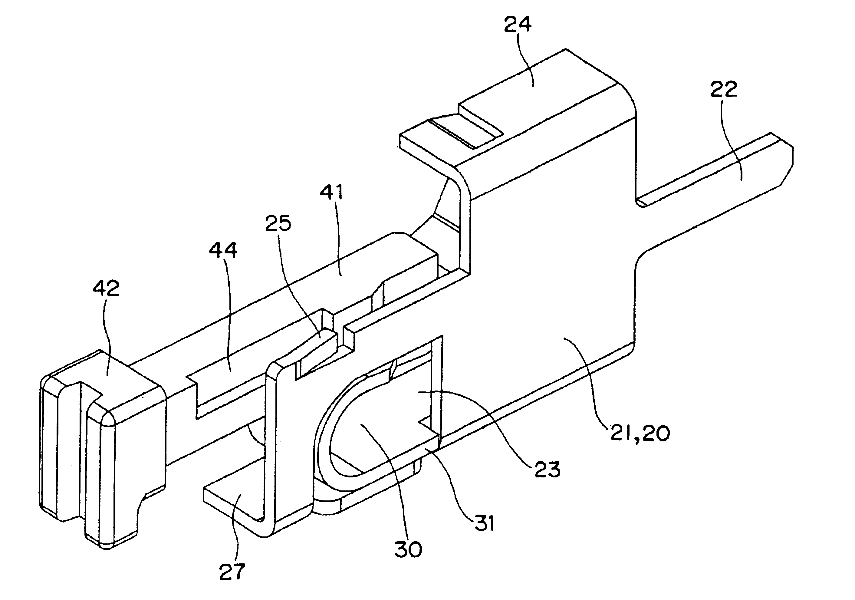
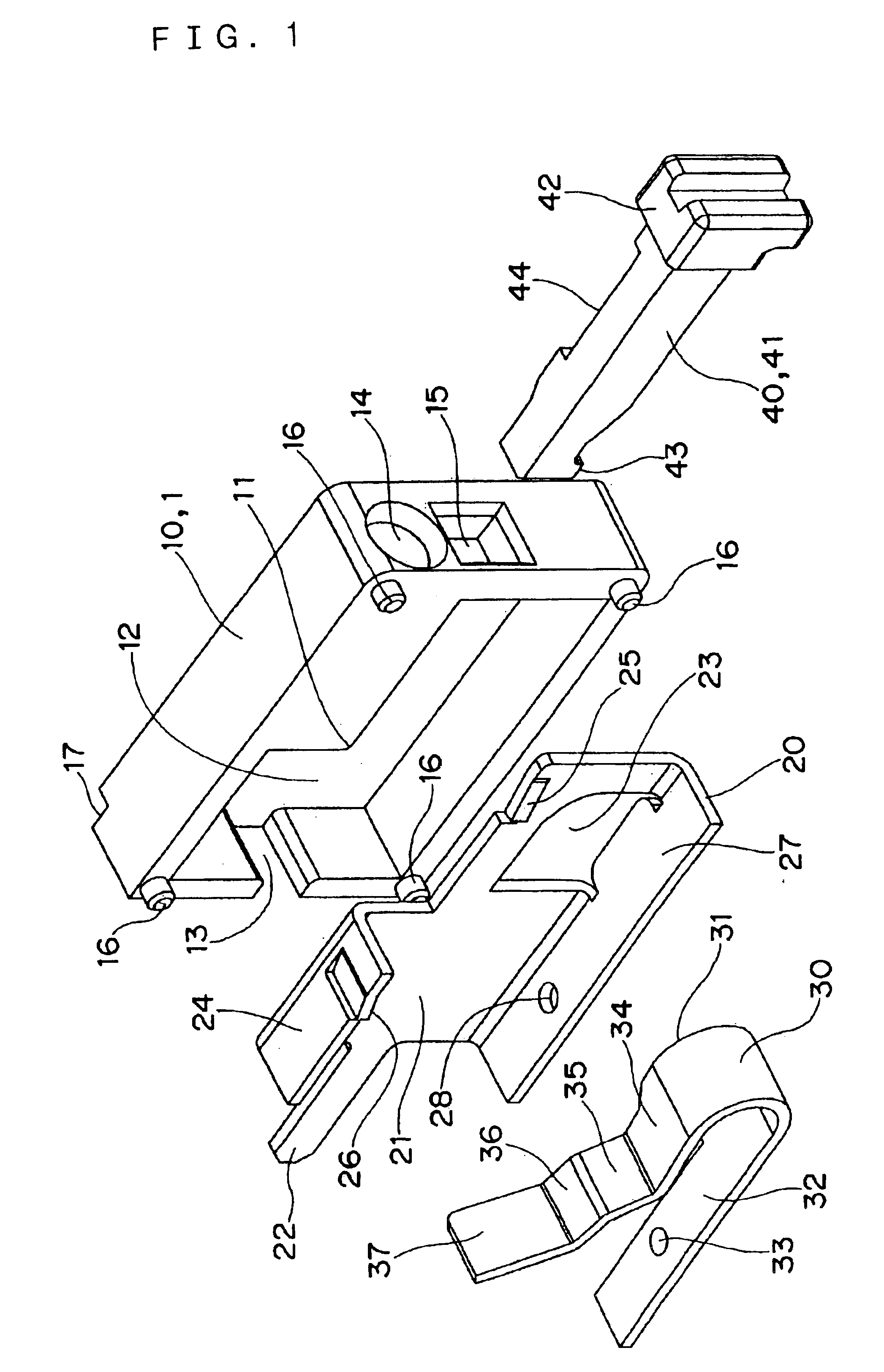
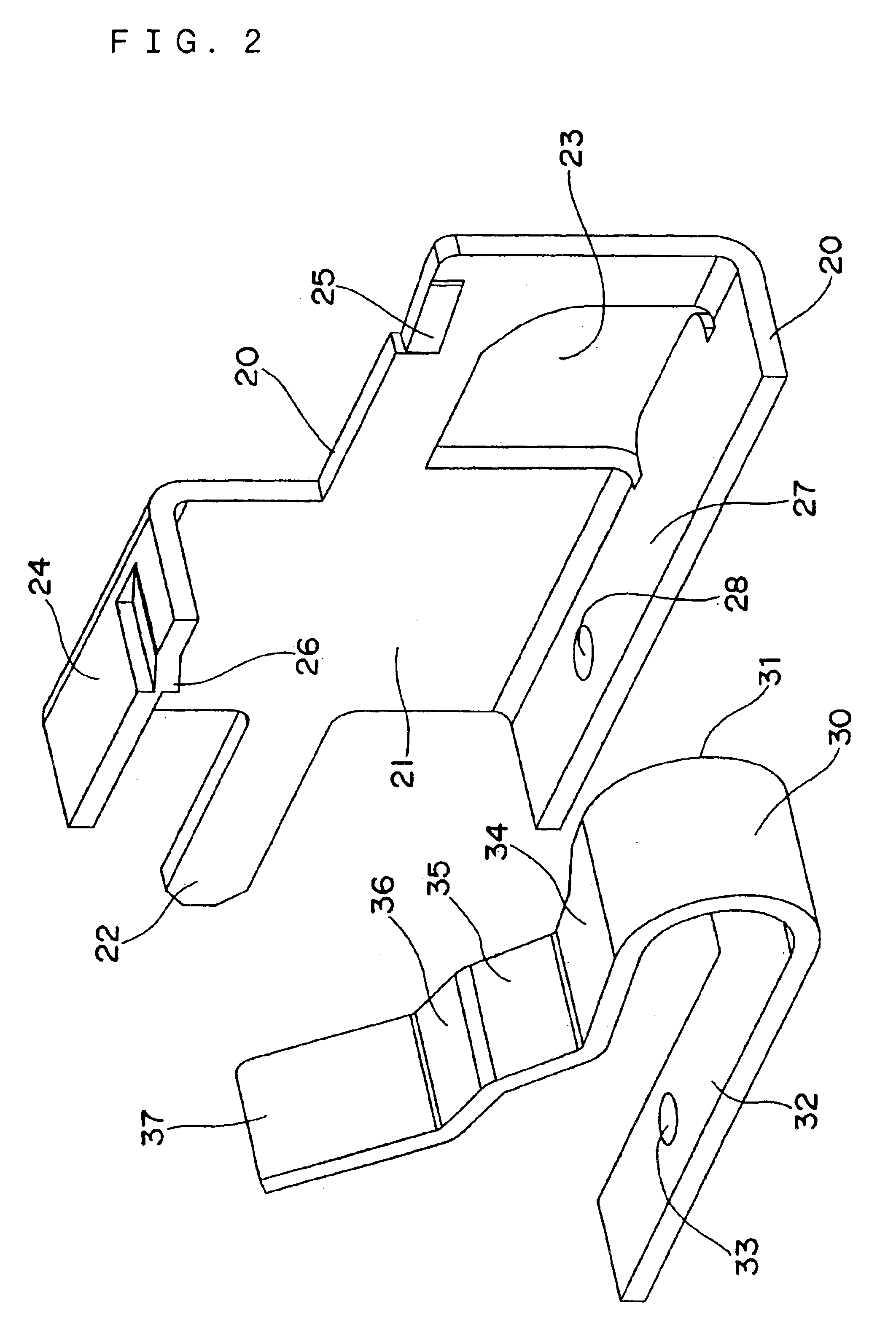
[0109]a wire connector according to the present invention is directed to a connector 1 for wire connection which substantially comprises, as shown in FIG. 1 to FIG. 13, a casing 10, a conductive fitting 20, a leaf spring 30, a manipulation button 40, and a cover 50.

[0110]The casing 10 is a box having a rectangular parallelepiped shape and defines an approximately L-shaped recessed portion 12 by forming a position restricting corner portion 11 in the inside thereof. A notched portion 13 into which a terminal described later is fitted is formed in one of opposing side end faces, while a wire insertion hole 14 and a manipulation button insertion hole 15 are formed in the other of the opposing side end faces. Further, with respect to the casing 10, positioning projections 16 are projected from corner portions of an open-side front face, while recessed portions 17 into which the projections 16 are fitted are formed in corner portions of a back face.

[0111]When necessary, push-insertion ho...

second embodiment

[0123]A connector 1 for wire connection according to the present invention is, as shown in FIG. 14 to FIG. 16, applicable to a case in which two wires are connected substantially coaxially. Here, the connector 1 for wire connection according to this embodiment is substantially comprised of a casing 10, a conductive fitting 20, leaf springs 30, 30, and manipulation buttons 40, 40 and a cover 50.

[0124]The casing 10 is formed of a box having a rectangular parallelepiped shape and an inverse T-shaped recessed portion 12 is defined by forming a pair of position restricting corner portions 11, 11 in the inside thereof. In opposing both-side end faces, wire insertion holes 14 and a manipulation button insertion hole 15 are respectively formed coaxially. Further, with respect to the casing 10, while positioning projections 16 are projected from corner portions of an open-ended side front face thereof, recessed portions 17 into which the projections 16 can be fitted are formed at corner port...

third embodiment

[0134]The third embodiment is directed to a case in which the invention is applied to a connector 1 for wire connection which is, as shown in FIG. 17 to FIG. 22, substantially comprised of a casing 10, a conductive fitting 20, a leaf spring 30, a manipulation button 40, a cover 50 and a lever 60.

[0135]The casing 10 is a box having a rectangular parallelepiped shape and defines an approximately L-shaped recessed portion 12 by forming a position restricting corner portion 11 in the inside thereof. A notched portion 13 into which a terminal is fitted is formed in one of opposing side end faces, while a wire insertion hole 14 and a manipulation button insertion hole 15 are formed in the other opposing side end face. Further, with respect to the casing 10, positioning projections 16 are projected from corner portions of an open-side front face, while recessed portions 17 into which the projections 16 can be fitted are formed in corner portions of a back face.

[0136]The conductive fitting ...


PUM


Abstract

In a wire connector, when a manipulation button 40 is pushed into a casing 10, a manipulation portion 43 of the manipulation button 40 pushes down one side of a leaf spring 30, whereas by pressing and locking an upper surface of the manipulation button 40 to a corner portion 11 of the casing 10 due to a reaction of the leaf spring 30. Accordingly, it is possible to provide the small wire connector which is simple in structure, high in reliability of contact, and easy in assembly and connecting operation.

Description

TECHNICAL FIELD[0002]The present invention relates to a wire connector which is referred to as a relay connector, a self-locking terminal device, a connector for wire connection or a relay terminal.BACKGROUND ART[0003]The prior art and the first task to be solved by the present invention[0004]Conventionally, as a wire connector, there has been known a relay connector provided with plugs and the like which is described in JP-A-10-12294, for example.[0005]That is, here described is a relay connector having a structure which holds an open state by engaging release buttons 11, 25 with outer peripheral surfaces of base housings 5, 19. However, in the above-mentioned conventional example, it is necessary to form engaging catching portions in the base housings 5, 19 and the structure becomes complicated and, at the same time, the miniaturization of the device becomes difficult.[0006]On the other hand, JP-UM-B-8-2924 discloses a self-locking terminal device as a type of wire connector.[0007...

Claims


Application Information

Patent Timeline
IPC IPC(8): H01R4/48H01R9/24
CPCH01R9/2408H01R4/48365H01R9/24
Inventor MIYOSHI, KAZUAKIKUMAGAI, JUNICHIROYAMADA, HISAKAZUTOMIZU, MOTOYUKI
Owner ORMON CORP
Why Eureka
Try Eureka