Method for designing a selective RF pulse for use in a magnetic resonance apparatus

a magnetic resonance apparatus and design method technology, applied in the field of selective rf pulse design for use in the magnetic resonance apparatus, can solve the problems that the design problem of selective rf pulses is generally not linear, and achieve the effect of reducing the dynamic range of magnetic resonance signals and reducing the dynamic rang

Inactive Publication Date: 2005-02-08
SIEMENS HEATHCARE GMBH
View PDF9 Cites 11 Cited by
  • Summary
  • Abstract
  • Description
  • Claims
  • Application Information

AI Technical Summary

Benefits of technology

For example, the spin magnetization can be advantageously set such that it is just re-phased by a prescribable gradient-time integral, or the azimuth phase distribution can be set with a quadratic curve in order, for example, to reduce the dynamic range of the magnetic resonance signals to be acquired via the phase

Problems solved by technology

Due to non-linearities of Bloch's equations, the design problem

Method used


Image

  • Method for designing a selective RF pulse for use in a magnetic resonance apparatus
  • Method for designing a selective RF pulse for use in a magnetic resonance apparatus
  • Method for designing a selective RF pulse for use in a magnetic resonance apparatus

Examples


Embodiment Construction

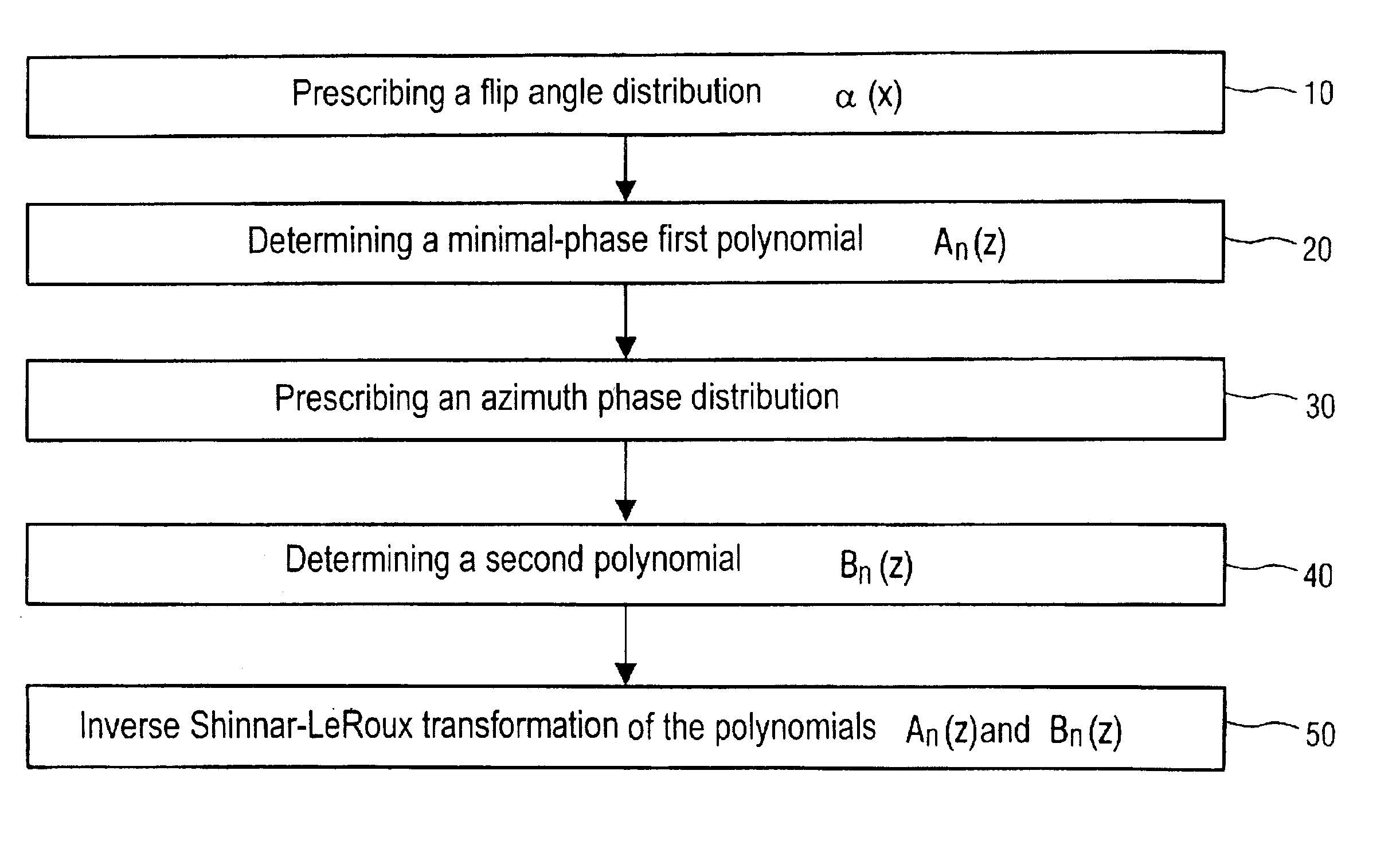
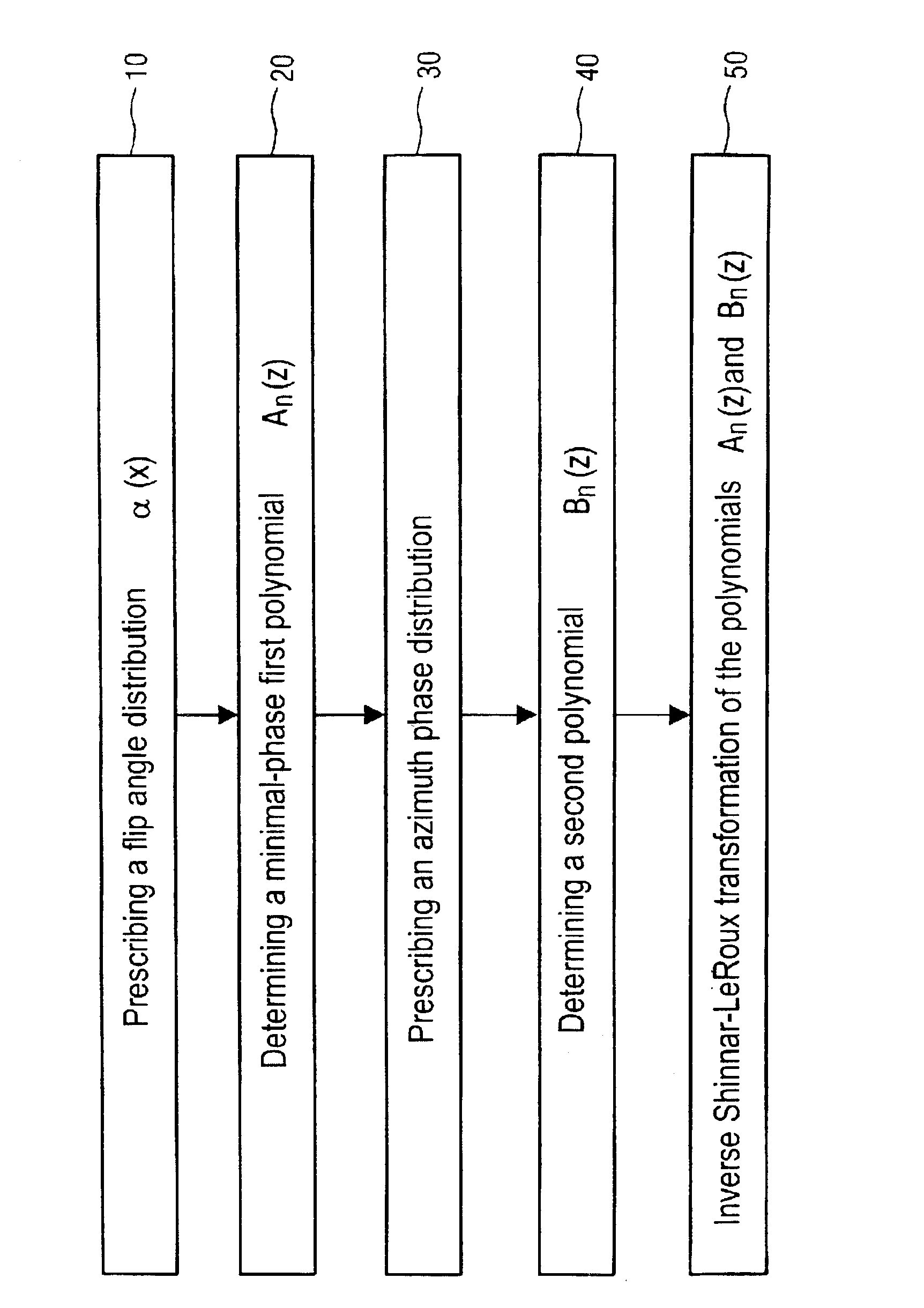
As an exemplary embodiment of the invention, the figure illustrates a flowchart for a method for designing a selective RF pulse for a magnetic resonance apparatus, based on a determination of a first polynomial An(z) and of a second polynomial Bn(z) that are Shinnar-LeRoux transforms of the RF pulse. The definition of the complex variable z as z=eiγGxΔt effects a presentation of the polynomial Bn(z) on a circle with radius 1, wherein γ is the gyromagnetic ratio, G is the selection gradient amplitude and Δt is the duration of a section of the imagined RF pulse divided into many constant sections. In order to obtain an RF pulse design method that allows setting of a freely prescribable azimuth phase distribution in the context of Shannon's sampling theorem, a flip angle distribution α(x) is first prescribed in the desired way via the selection gradient direction x in a first step 10. As described above, the magnitude of the second polynomial |Bn(eiγGxΔt)| is equal to the sine of half ...


PUM


Abstract

In a method for designing a selective RF pulse for a magnetic resonance apparatus, based on a determination of a first polynomial (An(z)) and a second polynomial (Bn(z)) that are Shinnar-LeRoux transforms of the RF pulse, a flip angle distribution (α(x)) to be achieved with the RF pulse is prescribed, the first polynomial (An(z)) is determined proceeding from the flip angle distribution (α(x)), the phase distribution of the transverse magnetization to be achieved with the RF pulse is prescribed, and the second polynomial (Bn(z)) is determined such that the magnitude is determined by the flip angle distribution (α(x)) and the phase thereof corresponds to a sum of the prescribed phase distribution and the phase of the, first polynomial (An(z)).

Description

BACKGROUND OF THE INVENTION1. Field of the InventionThe present invention on is directed to a method for designing a selective RF pulse for use in a magnetic resonance apparatus, as well as to a selective RF pulse designed in accordance with the method.2. Description of the Prior ArtMagnetic resonance is a known technology for, among other things, acquiring images of the inside of the body of an examination subject. In a magnetic resonance apparatus, rapidly switched gradient fields that are generated by a gradient coil system are thereby superimposed on a static basic magnetic field that is generated by a basic field magnet. The magnetic resonance apparatus also has a radiofrequency (RF) system that emits radiofrequency energy into the examination subject for triggering magnetic resonance signals and picks up the magnetic resonance signals, on the basis of which magnetic resonance images are produced.When the examination subject is thereby exposed to the static, homogeneous basic m...

Claims


Application Information

Patent Timeline
IPC IPC(8): G01R33/48G01R33/44G01R33/46G01R33/483
CPCG01R33/446G01R33/4833G01R33/4616
Inventor HEID, OLIVER
Owner SIEMENS HEATHCARE GMBH
Why Eureka
Try Eureka