
Image forming device and toner device

a technology of toner device and developing roller, which is applied in the direction of optics, electrographic process apparatus, instruments, etc., can solve the problems of difficult to press the developer unit against the photosensitive drum with stable pressure, difficult to even press the developing roller against the photosensitive drum, etc., to enhance the safety and reliability of operation, simple structure, and easy exchange

Inactive Publication Date: 2005-02-08
SHARP KK
View PDF5 Cites 8 Cited by
  • Summary
  • Abstract
  • Description
  • Claims
  • Application Information

AI Technical Summary

Benefits of technology

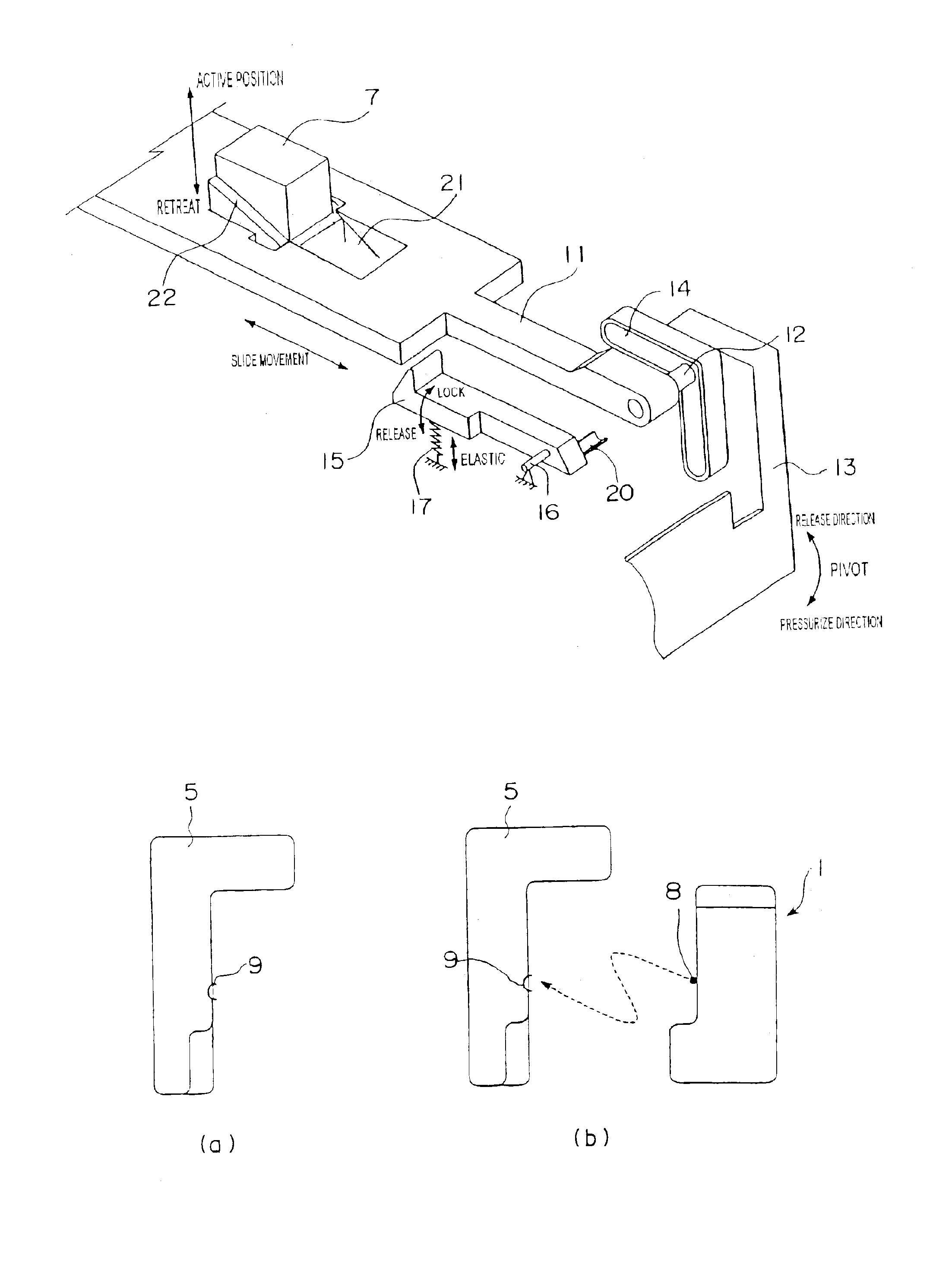
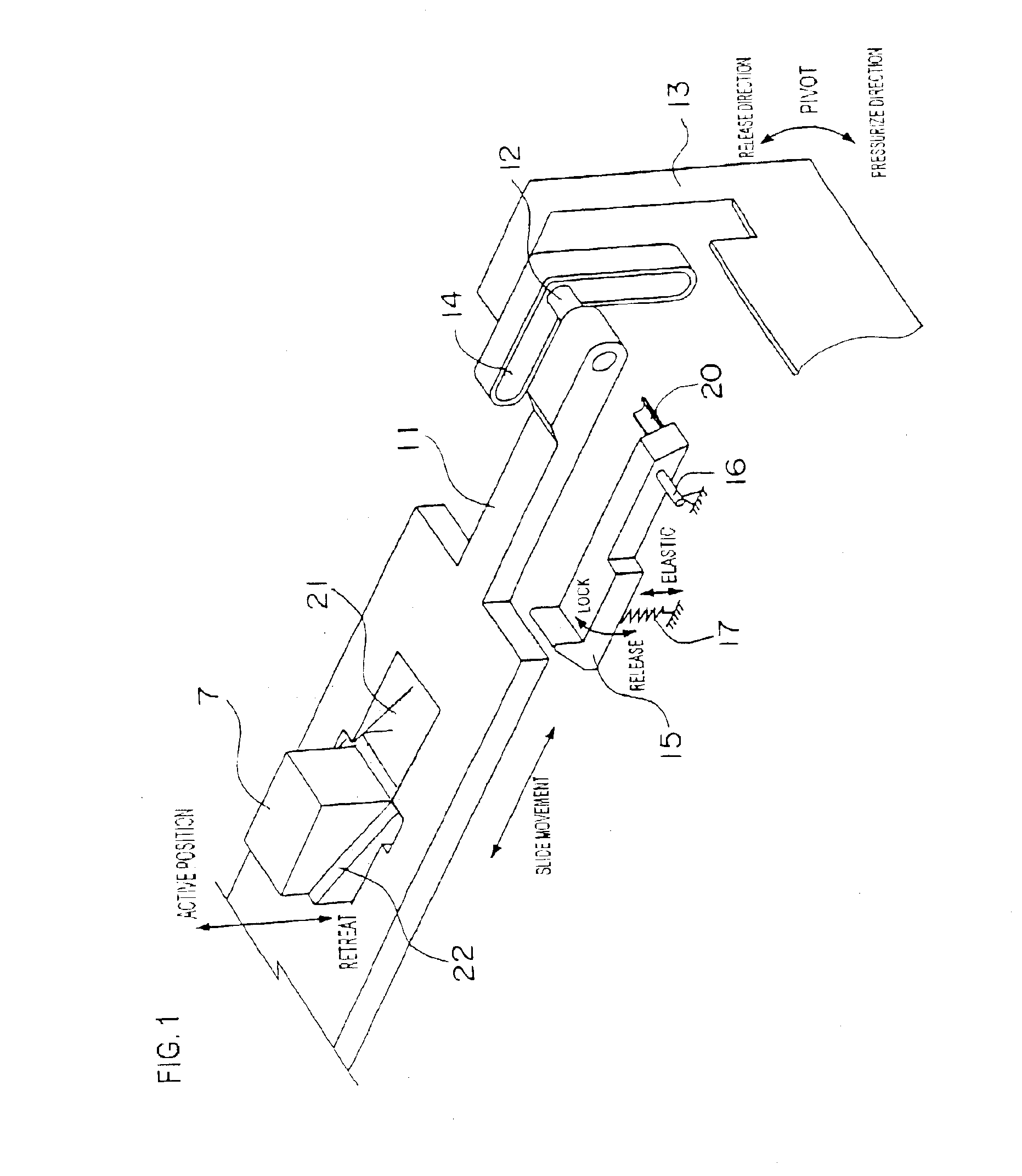
The present invention aims to solve problems in the prior art by providing a toner cartridge with a simple structure that allows for easy exchange, uniform pressure between the photosensitive drum and the developing roller, and increased safety and reliability of operation. The invention also provides an image forming device equipped with the toner cartridge. The toner cartridge comprises a biasing force generating means, an actuating rod, a lock member, and a manipulation member that interconnects with each other. The manipulation member causes the actuating rod to switch the biasing force generating means between a released state and a non-active state, and the lock member to pivot between a locked state and an unlocked state. The sliding / pivoting motion of the manipulation member causes the lock member to move and either release or fix the developer casing to the image forming device. The biasing force generating means disposed at plural areas on the toner cartridge release in synchronization with the pivoting operation of the manipulation member, causing the developing roller to be pressed against the photosensitive drum. The image forming device comprises the toner cartridge mentioned above.

Problems solved by technology

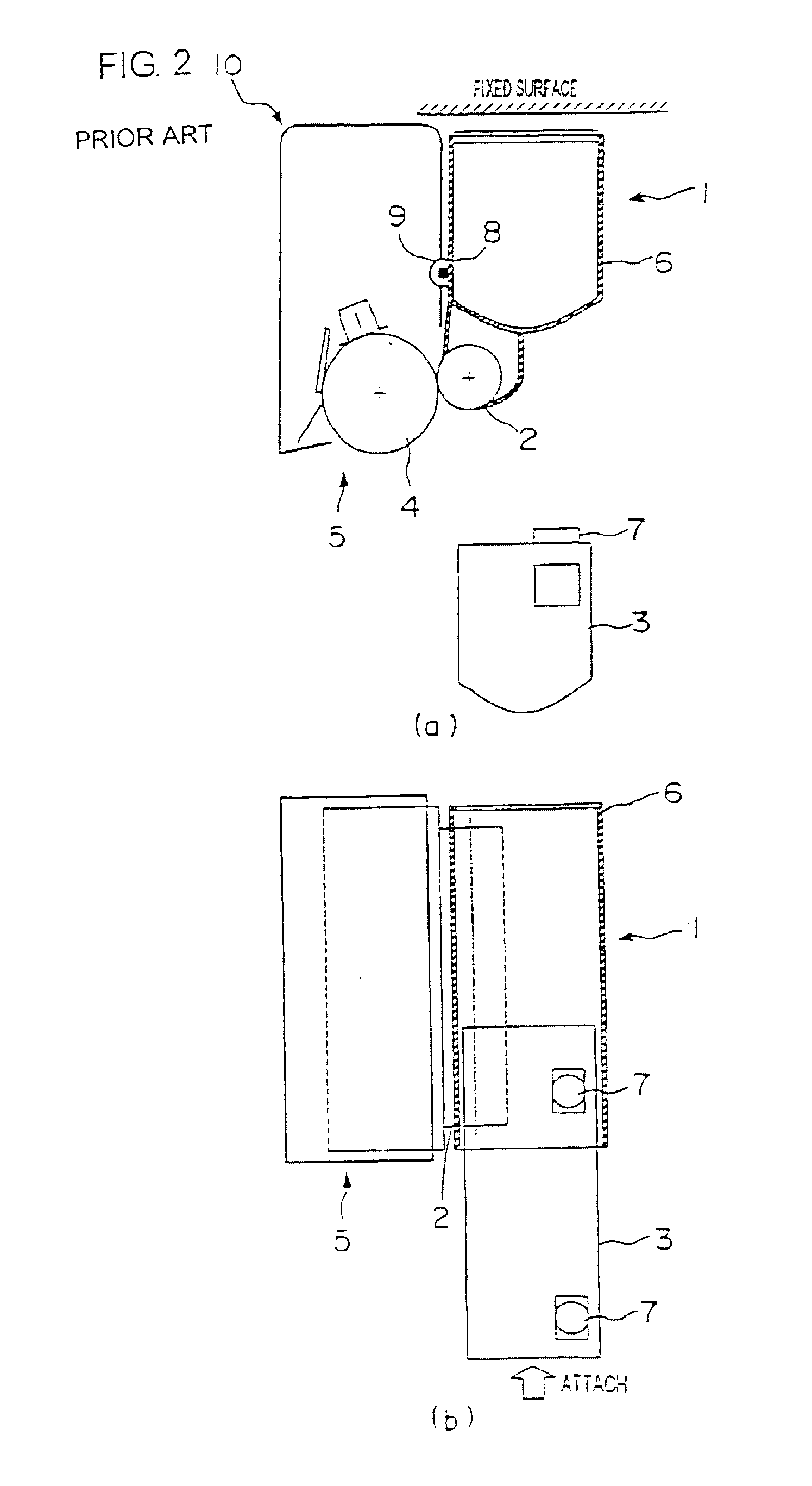
According to the above-mentioned image forming device, the inner structure of the image forming device is complicated, equipped with operating members, link mechanism and the like to press the developing roller against the photosensitive drum.
It is difficult to press the developing roller against the photosensitive drum with even pressure when using the pressurizing force provided by the operating members and the link mechanism.
That is, since the above device adopts a structure supporting the relatively heavy developer unit from underneath with a stay so as to enable swinging movement of the developer unit, it is difficult to press the developer unit against the photosensitive drum with stable pressure.
When a pressurizing member and a link mechanism are used in the image forming device, the spring length becomes extremely unstable due to the accumulated dispersion of the size accuracy of the members themselves, the accuracy of assembly, the deformation of members during operation and so on.

Method used


Image

  • Image forming device and toner device
  • Image forming device and toner device
  • Image forming device and toner device

Examples


examples

We will now explain a few examples of the toner cartridge 3 and the image forming device equipped with the toner cartridge 3 according to the present invention.

FIG. 8 is a perspective view of the toner cartridge 3, and in the drawing, the same reference numbers that appeared in the previous description refer to the components having the same name, structure and assembly (the same can be said for the following explanations).

In the drawing, the release lever 13 takes its pressurizing position (vertical direction), along with which the biasing force generating means 7 is released and the lock member 15 operated, but this is merely illustrated for explaining the combination of the components of the toner cartridge 3, and is not the ordinary state.

If the toner cartridge 3 is taken out alone, the release lever 13 is at a released position (horizontal direction), and the other related components take their positions accordingly, as shown in FIG. 10.

FIG. 9 is a perspective view showing the ...


PUM


Abstract

A toner cartridge stored in a developer casing includes a biasing force generating device, an actuating rod that switches the biasing device between an active state and a non-active state by one movement of a release member. A developer casing swings by the movement of the actuating rod and presses a developing roller with appropriate pressure to a photosensitive drum. There is a lock member that is restrained from moving by the movement of the actuating rod. The structure recited is capable of inserting and fixing the developer casing to an image forming device. Also, by one restore movement of the release member, the photosensitive drum and the developing roller are separated and the lock is released, thereby enabling removal / exchange of the developer casing.

Description

FIELD OF THE INVENTIONThe present invention relates to a toner cartridge mounted on an image forming device for forming an image on a recording medium using electrophotographic technology (such as a copier or a printer), and an image forming device comprising this toner cartridge.DESCRIPTION OF THE RELATED ARTIn a conventional image forming device such as a copier or a laser printer, an electrostatic latent image is first formed on a surface of a photosensitive drum, and then the image is developed by a developing device to create a toner image.In general, the developing device comprises a developing device body for supplying toner to the electrostatic latent image on the photosensitive drum via a developing roller, and a toner casing for supplying the toner to the developing device body. The toner casing generally adopts an exchangeable cartridge system so that a user can easily exchange the toner casing equipped to the image forming device body when the toner is used up, the cartr...

Claims


Application Information

Patent Timeline
Patent Type & Authority Patents(United States)
IPC IPC(8): G03G15/08
CPCG03G15/087G03G15/0875
Inventor ISHIGURO, YASUYUKIKATO, KEIJINISHINO, TOSHIOINOUE, ATSUSHIOHGOSHI, TOSHIHIDEMIZOGUCHI, HUMITOYOSHIDA, WATARU
Owner SHARP KK
Learn More