Hydraulic valve system

Inactive Publication Date: 2005-02-15
SAUER DANFOSS NORDBERG
View PDF14 Cites 19 Cited by
  • Summary
  • Abstract
  • Description
  • Claims
  • Application Information

AI Technical Summary

Benefits of technology

The compensation valve has a slide, in which the second non-return valve is arranged. Thi

Problems solved by technology

Thus, the pressures ruling in the load-sensing line or at the directional valve, respectively, no longer exclusively and immediately control the compens

Method used


Image

  • Hydraulic valve system
  • Hydraulic valve system
  • Hydraulic valve system

Examples


Example

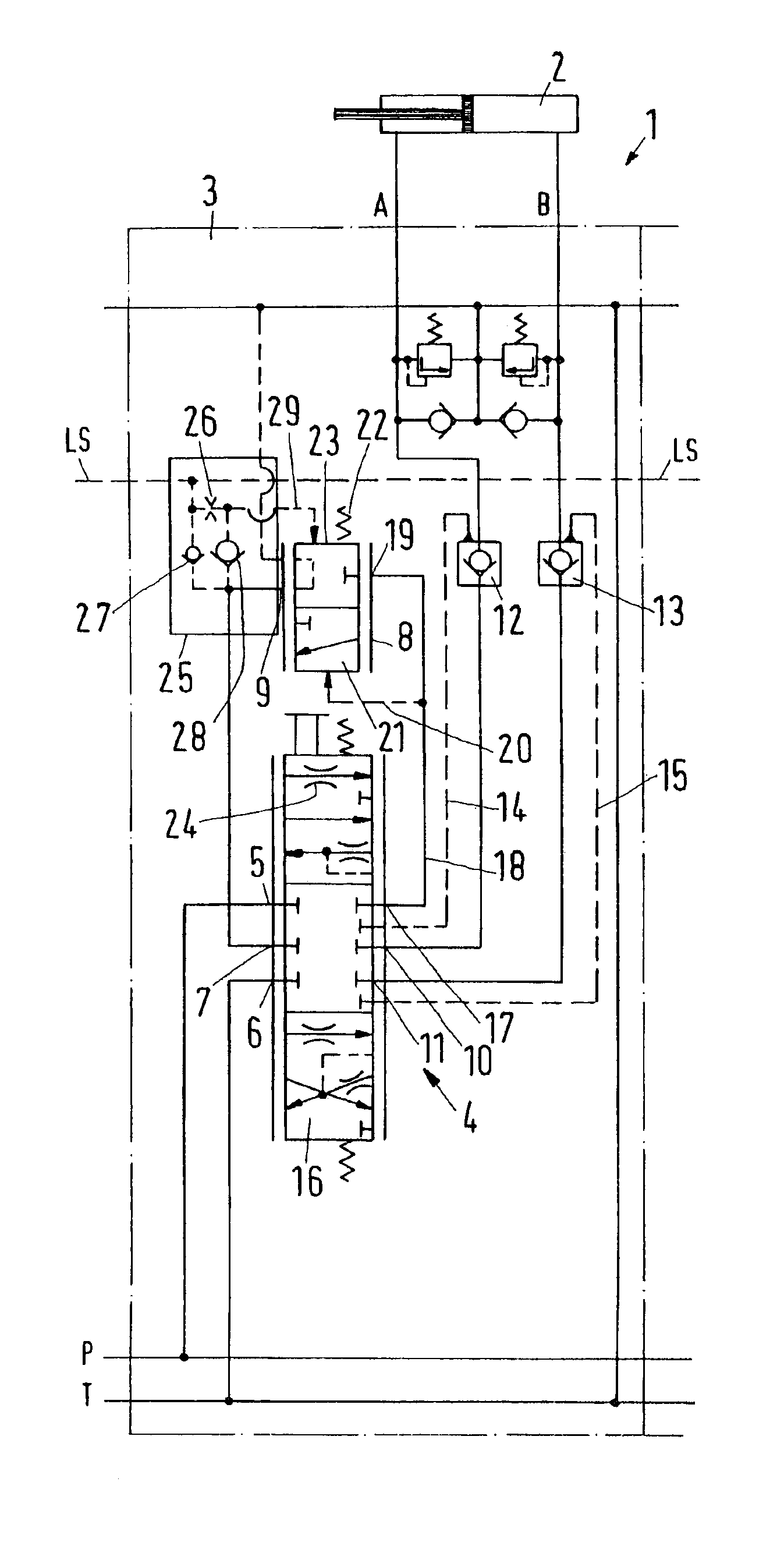
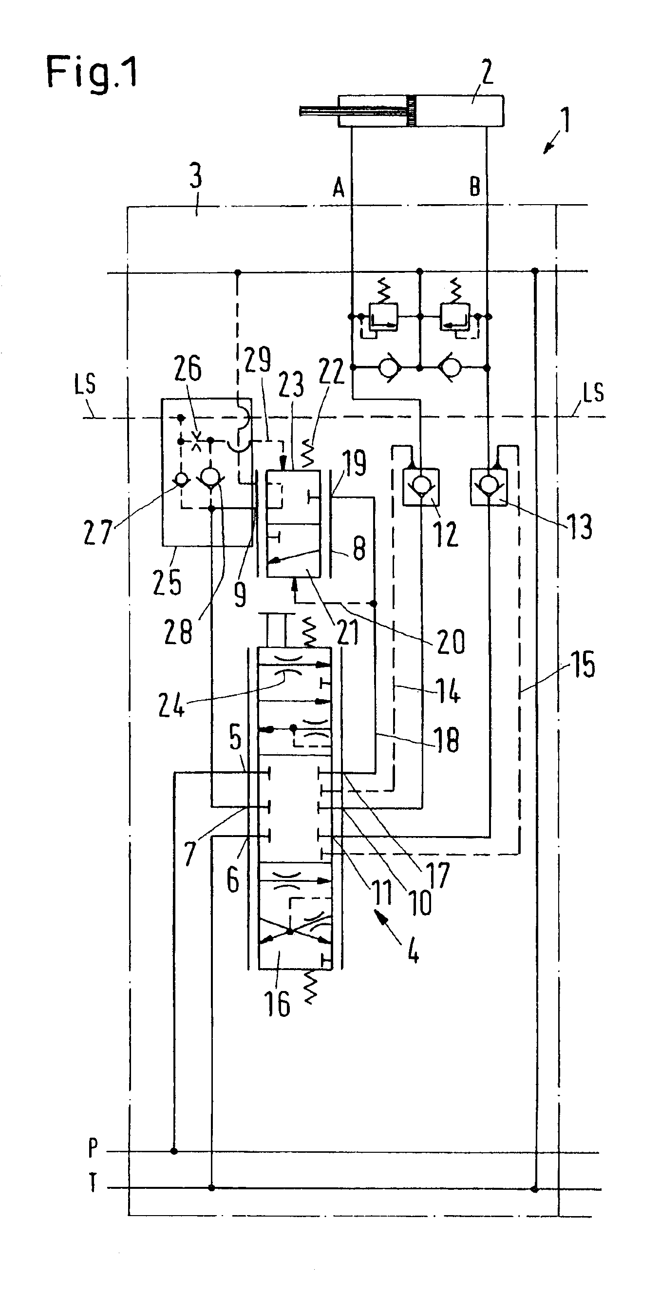
With reference to FIG. 1, a hydraulic valve system 1 for controlling a motor 2, in the present case in the form of a piston-cylinder arrangement, has a high-pressure connection P and a low-pressure connection T. Together, the high-pressure connection P and the low-pressure connection T form a supply connection arrangement, through which hydraulic fluid under pressure can flow from a pump (not shown in detail) to the valve system 1 and from here back to a tank (also not shown in detail). The valve system 1 is made as the module 3, which can be flanged together with other modules. Accordingly, the supply connection arrangement can also be connected with the supply connection arrangement of other modules.

The valve system 1 also has a working connection arrangement A, B, to which the motor 2 is connected. Between the supply connection arrangement P, T and the working connection arrangement A, B is arranged a directional valve 4, which supplies either the working connection A or the work...


PUM


Abstract

A hydraulic valve system (1) has a supply connection arrangement having a high-pressure connection (P) and a low-pressure connection (T), a working connection arrangement, having two working connections (A, B) connectable with a motor (2), with a directional valve (4), which is arranged between the supply connection arrangement (P, T) and the working connection arrangement (A, B), and with a compensation valve (8), which is acted upon in a first operation direction by a spring (22) and a pressure in a pressure chamber (23), which is connected with a load-sensing line (LS), and in a second operation direction, which is opposite to the first operation direction, by a pressure at the directional valve (4).

Description

BACKGROUND OF THE INVENTIONThe invention concerns a hydraulic valve system with a supply connection arrangement having a high-pressure connection and a low-pressure connection, a working connection arrangement, having two working connections connectable with a motor, with a directional valve, which is arranged between the supply connection arrangement and the working connection arrangement, and with a compensation valve, which is acted upon in a first operation direction by a spring and a pressure in a pressure chamber, which is connected with a load-sensing line, and in a second operation direction, which is opposite to the first operation direction, by a pressure at the directional valve.A valve system of this kind is known from, for example, DE 199 19 015 A1.A valve system of this kind is required for controlling a motor. In a hydraulically controlled working machine, such a motor is, for example, able to lift or lower a load. Such a valve system is particularly suited for contro...

Claims


Application Information

Patent Timeline
IPC IPC(8): E02F9/22F15B11/05F15B11/00F15B13/04F15B13/00
CPCE02F9/2207E02F9/2267E02F9/2271F15B11/003F15B11/05F15B13/0417E02F9/226F15B2211/8613F15B2211/30505F15B2211/3051F15B2211/30555F15B2211/3111F15B2211/3144F15B2211/31576F15B2211/324F15B2211/5059F15B2211/513F15B2211/5154F15B2211/528F15B2211/605
Inventor ZENKER, SIEGFRIEDCHRISTENSEN, THORKILD
Owner SAUER DANFOSS NORDBERG
Why Eureka
Try Eureka