Fuel vapor handling system

a technology of vapor handling system and vapor vapor, which is applied in the direction of combustion air/fuel air treatment, electric control, instruments, etc., can solve the problems of troublesome leak detection, troublesome leak detection, and difficulty in ensuring stability suitable for leak detection, so as to prevent leak detection errors

Inactive Publication Date: 2005-02-15
DENSO CORP
View PDF8 Cites 3 Cited by
  • Summary
  • Abstract
  • Description
  • Claims
  • Application Information

AI Technical Summary

Benefits of technology

[0013]The leak detection error can be prevented for example by canceling a result of the check by the check means, or by discontinuing a check procedure by the check means.

Problems solved by technology

During engine operation, however, it is difficult to ensure stability suitable for leak detection because of changes in the operating condition of the engine and the movement of a motor vehicle.
On the other hand, leak can be detected while the engine is at a stop.
However, even after the engine is stopped, there occurs an event which disturbs leak detection, such as the opening of a filler cap of the fuel tank to fill the fuel to the engine.

Method used


Image

  • Fuel vapor handling system
  • Fuel vapor handling system
  • Fuel vapor handling system

Examples


first embodiment

[0025][First Embodiment]

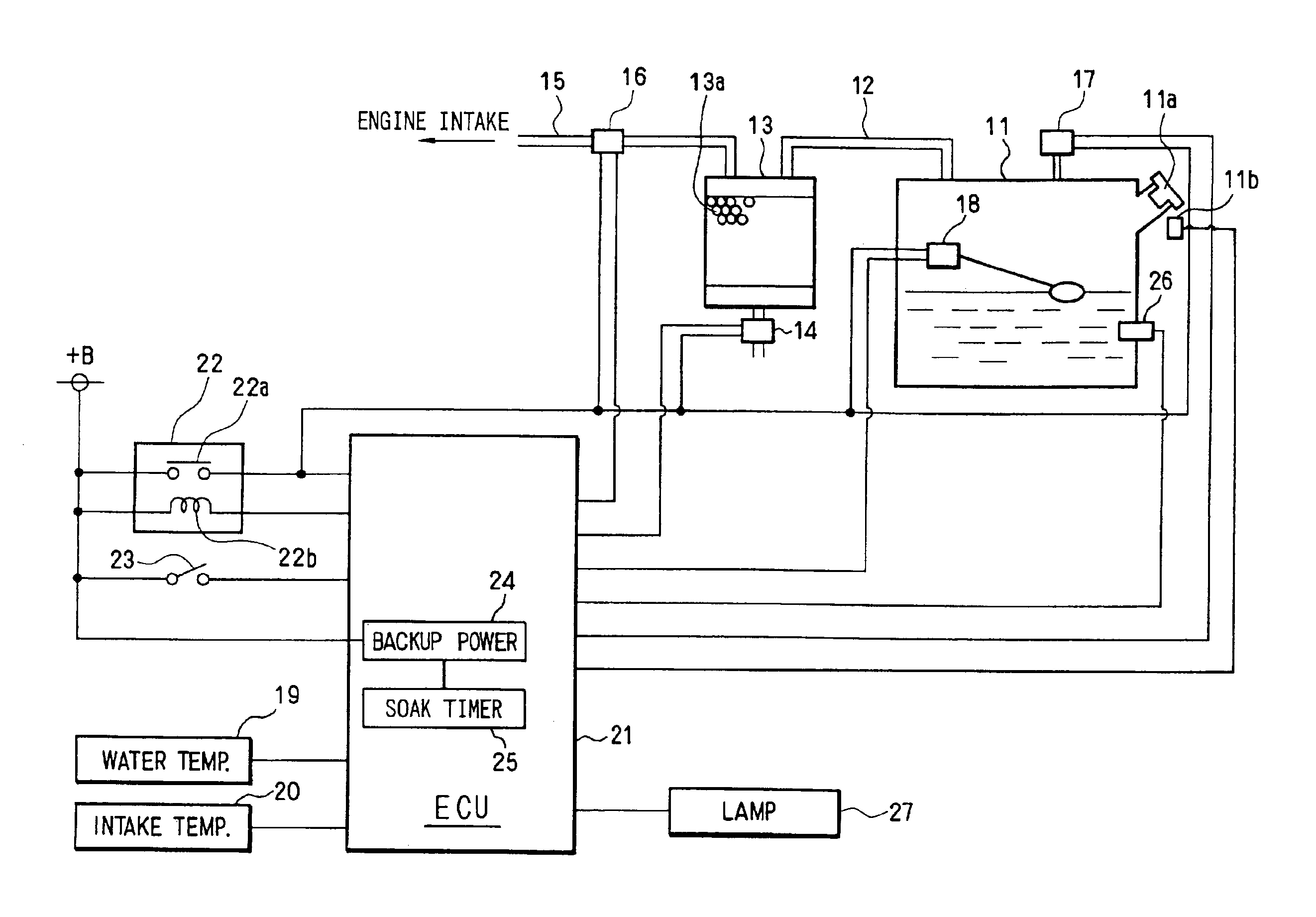
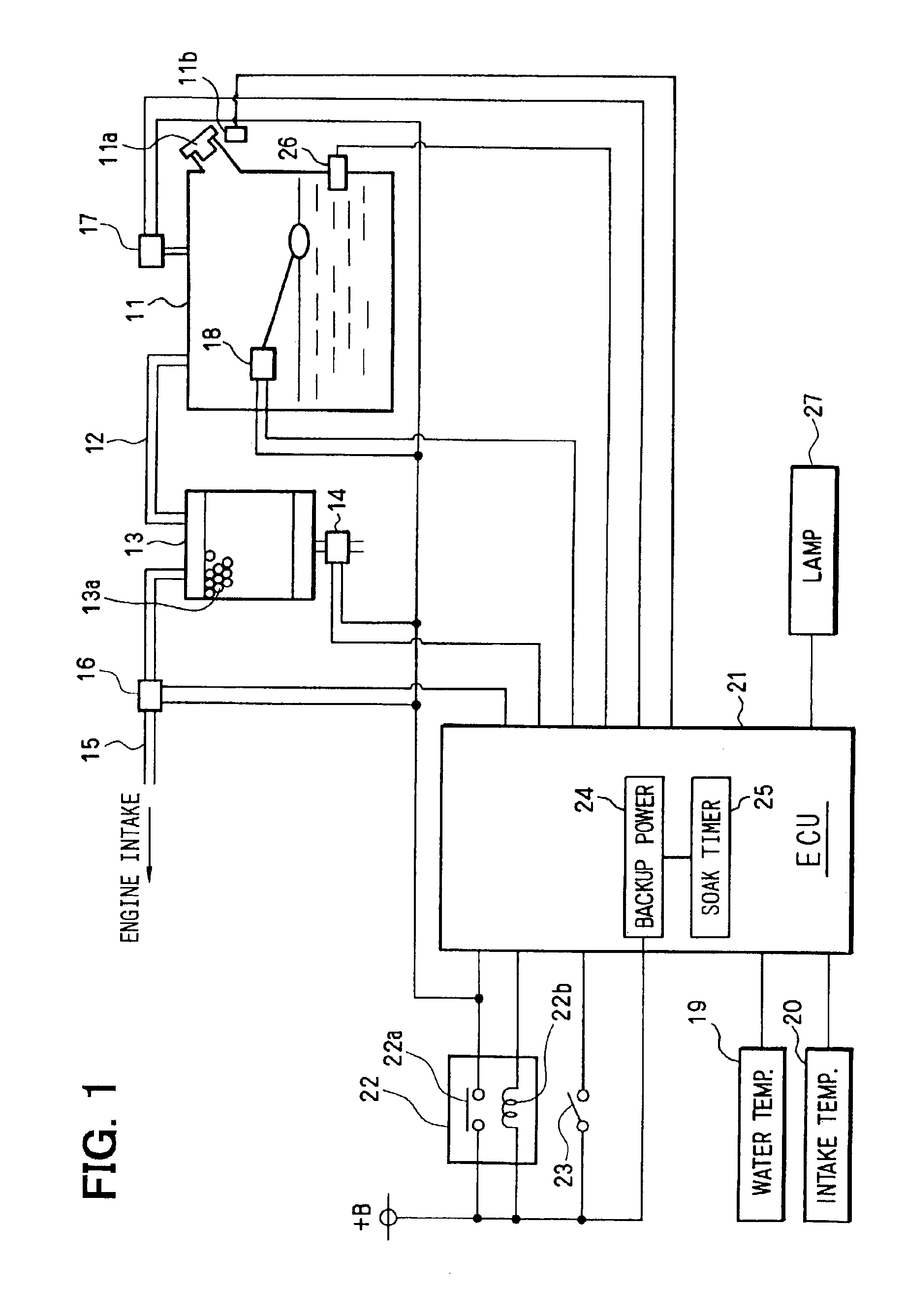
[0026]A fuel vapor handling system according to the first embodiment of this invention will be described below with reference of FIGS. 1 to 5. First, the structure of the fuel vapor handling system will be explained by referring to FIG. 1. A canister 13 is connected to a fuel tank 11 through a fuel vapor passage 12. In the canister 13 is housed an adsorbent 13a, such as an activated carbon, for the adsorption of the fuel vapor. A canister valve 14 is attached to an air communicating port located at the bottom of the canister 13.

[0027]The canister valve 14 is a normally open type solenoid valve, which is in an open position when the power is off, holding the air communicating port of the canister 13 open to the atmosphere. When the power is supplied, however, the canister valve 14 is closed to also close the air communicating port of the canister 13.

[0028]On the other hand, connected between the canister 13 and an engine intake system is a purge passage 15 for...

second embodiment

[0060][Second Embodiment]

[0061]If the filler cap is opened after the end of a leak check even when the filler cap was opened when the engine is at a stop, the result of the leak check will not be affected by opening the filler cap.

[0062]In the second embodiment of this invention, in view of the circumstances stated above, the leak check will be aborted when it is determined that the filler cap was opened prior to the end of the leak check.

[0063]Now, description will be given below of a leak check control base routine shown in FIG. 6 and details of the processing of the main relay control routine shown in FIG. 7 both used in the present second embodiment.

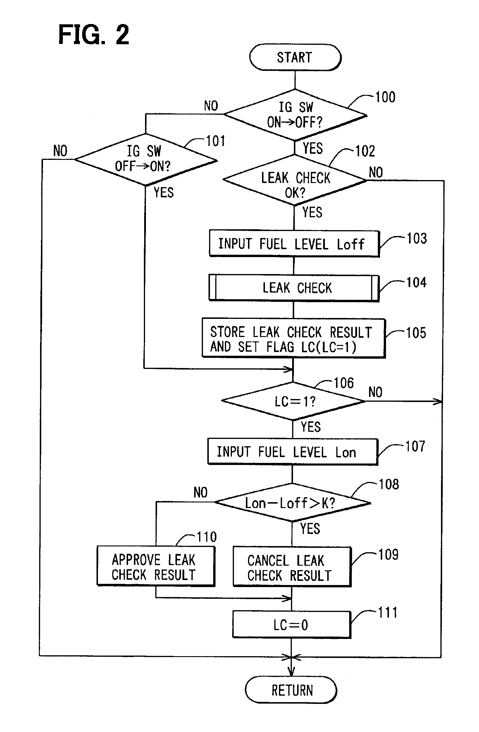
[0064]At Step 401, a determination is made on that the IG switch 23 is turned OFF. At Step 402, it is determined whether the conditions necessary for executing the leak check have been established. When the conditions for executing the leak check have been established, the leak check routine of FIG. 3 will be executed at Step 403. At...

third embodiment

[0069][Third Embodiment]

[0070]Next, the third embodiment of this invention will be explained with reference to FIGS. 8 to 10.

[0071]When the filler cap of the fuel tank 11 is opened during the period of leak check after the engine stopped, the tank pressure suddenly drops to the vicinity of the atmospheric pressure as indicated by a two-dot chain line in the time chart of FIG. 10. The tank pressure is maintained at the atmospheric pressure, thereafter gradually increasing when the supply of fuel is commenced with a filler nozzle inserted into a filler port.

[0072]In the third embodiment, the leak check is interrupted in response to a change in tank pressure.

[0073]Next, processing in the leak check routines to be executed in the present embodiment will be explained in detail with reference to FIGS. 8 and 9. When the leak check executing conditions similar to those in the first embodiment are established after an engine stop (Steps 501 and 502), the routine proceeds to Step 503. At Step...


PUM


Abstract

In a fuel vapor handling system of this invention, an ECU performs a leak check to check a leak of fuel vapor in a fuel vapor passage when the engine is at a stop. The ECU functions to detect the quantity of fuel during the engine stop. The ECU detects the quantity of fuel at the time of engine starting. Furthermore, the ECU compares the quantity of fuel measured at the time of engine starting with the quantity of fuel measured at the preceding engine stop, to thereby determine whether a filler cap was opened during the engine stop. When the filler cap was opened during the engine stop, a result of the leak check will be cancelled. When the filler cap was not opened, the result of the leak check will be determined.

Description

CROSS REFERENCE TO RELATED APPLICATION[0002]This application is based on Japanese Patent Application No. 2001-320468 filed on Oct. 18, 2001 the contents of which are incorporated herein by reference.BACKGROUND OF THE INVENTION[0003]1. Field of the Invention[0004]This invention relates to a fuel vapor handling system for handling fuel vapor present in a fuel tank, and more particularly to a system equipped with a leak check device which detects a vapor leak in a passage including the fuel tank.[0005]2. Description of Related Art[0006]There has been known the adoption of a canister which traps fuel vapor for the purpose of preventing the discharge of the fuel vapor out of the fuel tank. Furthermore, also known is a fuel vapor handling system which is designed to drive out the fuel vapor trapped in the canister, to thereby supply the fuel vapor through an engine intake passage into the engine, in which the fuel vapor is combusted. This system is also called a fuel vapor purge system.[0...

Claims


Application Information

Patent Timeline
Patent Type & Authority Patents(United States)
IPC IPC(8): F02M25/08F02D41/04G01M3/26G01M15/04
CPCF02M25/0809F02D41/042
Inventor MORINAGA, SYUJIROMAEGAWA, YOSHINORIWAKAHARA, KEIJIMIWA, MAKOTO
Owner DENSO CORP
Why Eureka
Try Eureka